
Intumescent cover for a poke-through assembly

a technology of intumescent cover and assembly, which is applied in the direction of electrical apparatus casing/cabinet/drawer, gaseous cathode, coupling device connection, etc., can solve the problems of compromising fire-stop capability and inability to provide a stable rigid support structure of intumescent material

Active Publication Date: 2010-03-09
THOMAS & BETTS INT INC
View PDF45 Cites 6 Cited by
  • Summary
  • Abstract
  • Description
  • Claims
  • Application Information

AI Technical Summary

Benefits of technology

"The present invention provides a poke-through assembly for installation in a hole in a floor structure. The assembly includes an intumescent member, a base plate, and an intumescent enclosure. The intumescent member is disposed between the floor and the ceiling of the second working environment. The base plate supports the intumescent member and limits its expansion towards the second working environment. The assembly also includes an upper frame, at least one intumescent member, and an intumescent cover. The intumescent member is disposed below the upper frame and the cover supports it and surrounds it, impeding its expansion. The cover can be fixedly secured to the upper frame or coupled to a conduit disposed below it. The assembly provides a safe and effective means for installing a poke-through in a floor structure."

Problems solved by technology

However, the intumescent material does not generally provide a stable rigid support structure, especially when heated substantially.
This causes a loss of intumescent material, which can compromise the fire-stop capability for which it was intended.

Method used


Image

  • Intumescent cover for a poke-through assembly
  • Intumescent cover for a poke-through assembly
  • Intumescent cover for a poke-through assembly

Examples


Embodiment Construction

[0017]This invention pertains to a poke-through assembly with improved heat isolation features, particularly in the form of a cover for retaining the intumescent material used in a fire-rated electrical poke-through assembly. Also, the features of the present invention are relatively inexpensive, manufactured easily and quickly installed. Additionally, the features of the present invention can be retrofit into existing poke-through assemblies without replacing the entire assembly.

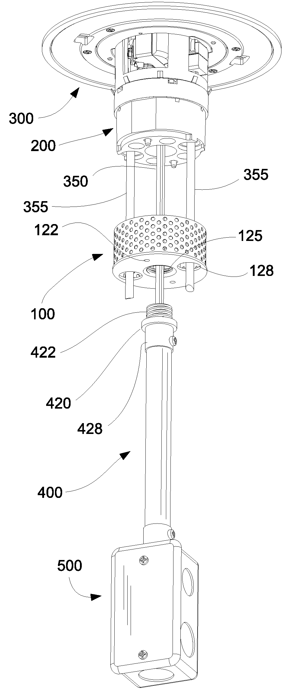
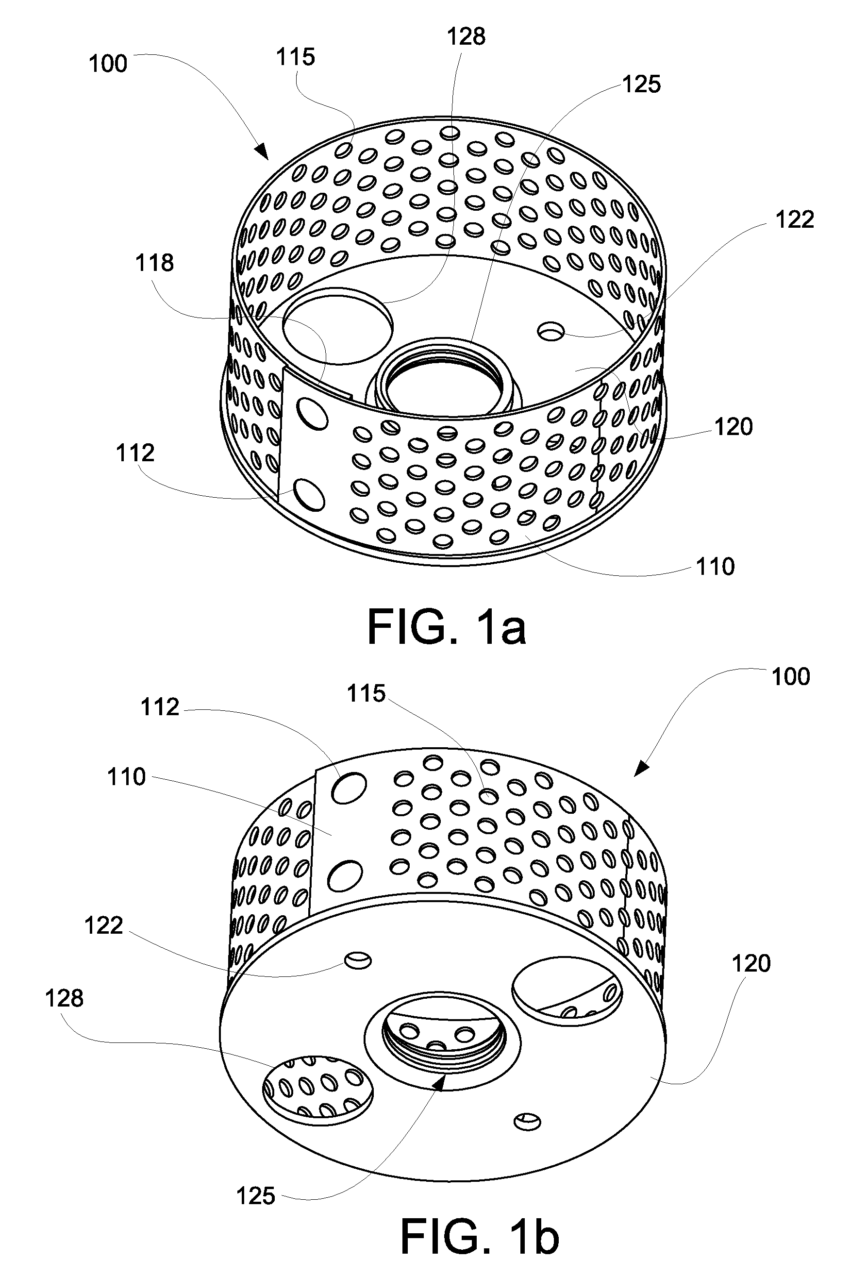
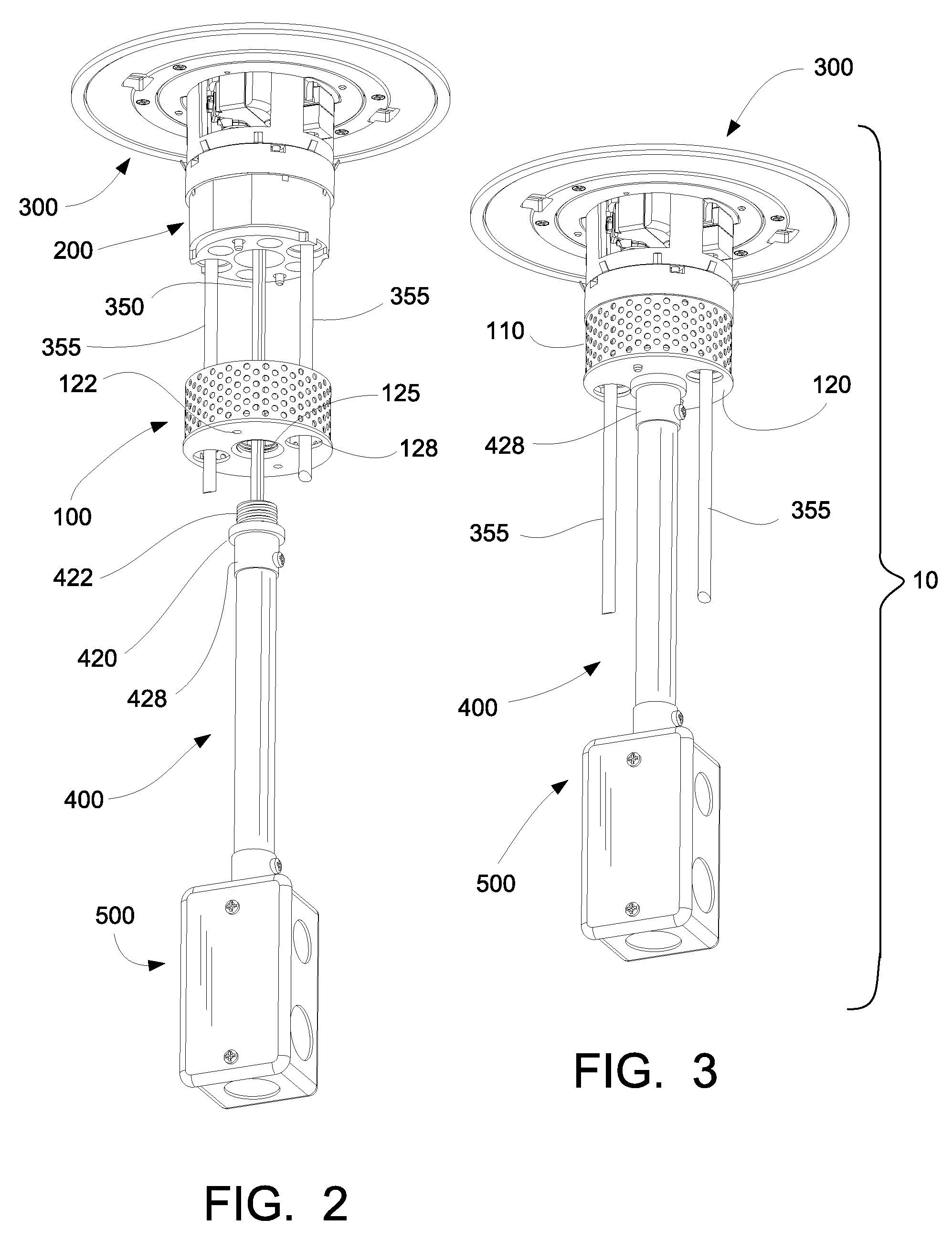
[0018]FIGS. 1a and 1b show an intumescent retainer or cover 100, in accordance with one embodiment of the present invention. The cover 100, preferably includes a perforated steel enclosure 110, in the form of an annular band that is attached to a steel lower plate 120. The enclosure 110 rises vertically from the lower plate 120, together forming a cup that can cover the lower portions of the poke-through assembly, and particularly the intumescent material (shown in FIGS. 2 and 3). Preferably, when fully ass...


PUM


Abstract

One aspect of the present invention provides a poke-through assembly for installation in a hole in a floor structure. The floor structure defines a floor in a first working environment and a ceiling in a second working environment. The poke-through assembly includes at least one intumescent member, a base plate and an intumescent enclosure. The intumescent member is disposed at least partially between the floor of the first working environment and the ceiling of the second working environment. The base plate supports and is disposed below the intumescent member for limiting the expansion of the intumescent member toward or into the second working environment. Another aspect of the present invention provides a poke-through assembly including an upper frame, at least one intumescent member and an intumescent cover. The intumescent member is disposed below the upper frame. The intumescent cover supports the intumescent member and circumferentially surrounds at least a portion of the intumescent member, wherein expansion of the intumescent member is impeded by the cover.

Description

CROSS-REFERENCE TO RELATED APPLICATIONS[0001]This application claims the benefit of U.S. Provisional Patent Application Ser. No. 60 / 868,944 filed on Dec. 7, 2006.BACKGROUND OF THE INVENTION[0002]A poke-through assembly or simply a “poke-through” is a common device that enables power, data or other cabling to pass through a hole between floors in a building, generally a concrete floor. A thermal barrier in the form of a fire and / or smoke retardant element, particularly intumescent material, is incorporated within the poke-through. The intumescent serves as a fire-stop and expands to seal any remaining space within the poke-through and the surrounding hole in which it is installed. This helps prevent the spread of fire and / or smoke from one floor to the next.[0003]Contemporary poke-throughs provide access between an upper floor and an immediately adjacent lower floor. The poke-through assembly is usually installed with a cover which serves as a cap or lid for the hole. Also, the poke-...

Claims


Application Information

Patent Timeline
Patent Type & Authority Patents(United States)
IPC IPC(8): H02G3/04
CPCH02G3/0493H02G3/185
Inventor DRANE, MARK R.JOLLY, ROBERT K.
Owner THOMAS & BETTS INT INC
Learn More