
Fluid cosmetic dispenser

a dispenser and liquid technology, applied in the field of liquid cosmetic dispensers, can solve the problems of separating from the bottle, affecting the appearance of the bottle, and the housing being taken out of alignment with the bottle, and risking spilling the contents of the dispenser

Inactive Publication Date: 2010-03-09
CONOPCO INC D B A UNILEVER
View PDF58 Cites 11 Cited by
  • Summary
  • Abstract
  • Description
  • Claims
  • Application Information

AI Technical Summary

Benefits of technology

This solution effectively prevents the housing from popping out of the bottle and reduces leakage, while minimizing the need for increased material volume, thus optimizing packaging efficiency and cost-effectiveness.

Problems solved by technology

When the cap is being either attached to or removed from the bottle, it imparts a turning force, so that if the point of attachment of the cap is on the housing rather than directly to the bottle, there is a risk of the housing being taken out of alignment with the bottle and in consequence impairing its styling, or even separating from the bottle.
Furthermore, even if a means is introduced to prevent relative rotation of housing and bottle, the further risk can remain of the housing separating from the bottle (colloquially, popping off) as a result of rotation-induced deformation thereby risking spilling the contents of the dispenser and particularly if the bottle and housing are both moulded from thermoplastic materials.
Although the likelihood of a housing separating from a bottle is recognisable when the mounting is directly onto the housing itself, a risk can also be contemplated if there is a significant turning force applied to the bottle that is in the vicinity of the mounting of housing on bottle.
Although these are problems that are immediately apparent for dispensers of fluids, they can be seen to apply to related dispensers which likewise employ a flow-regulating outlet which is mounted on a cosmetic container that is closed by a cap that is applied or removed by rotation.

Method used


Image

  • Fluid cosmetic dispenser
  • Fluid cosmetic dispenser
  • Fluid cosmetic dispenser

Examples


Embodiment Construction

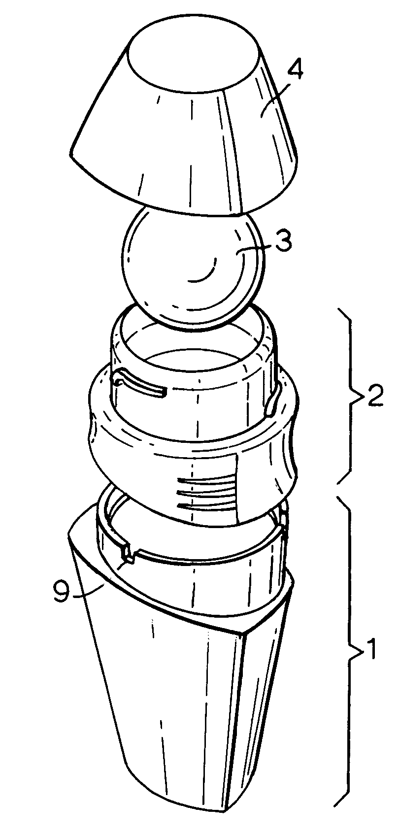
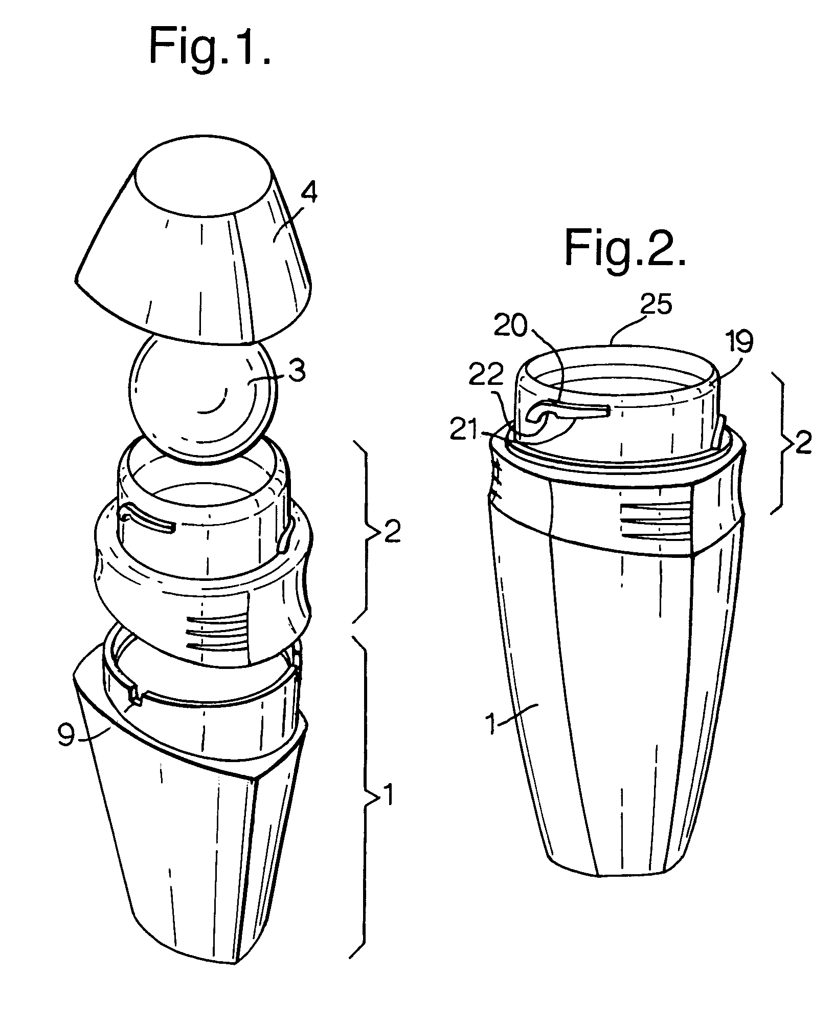
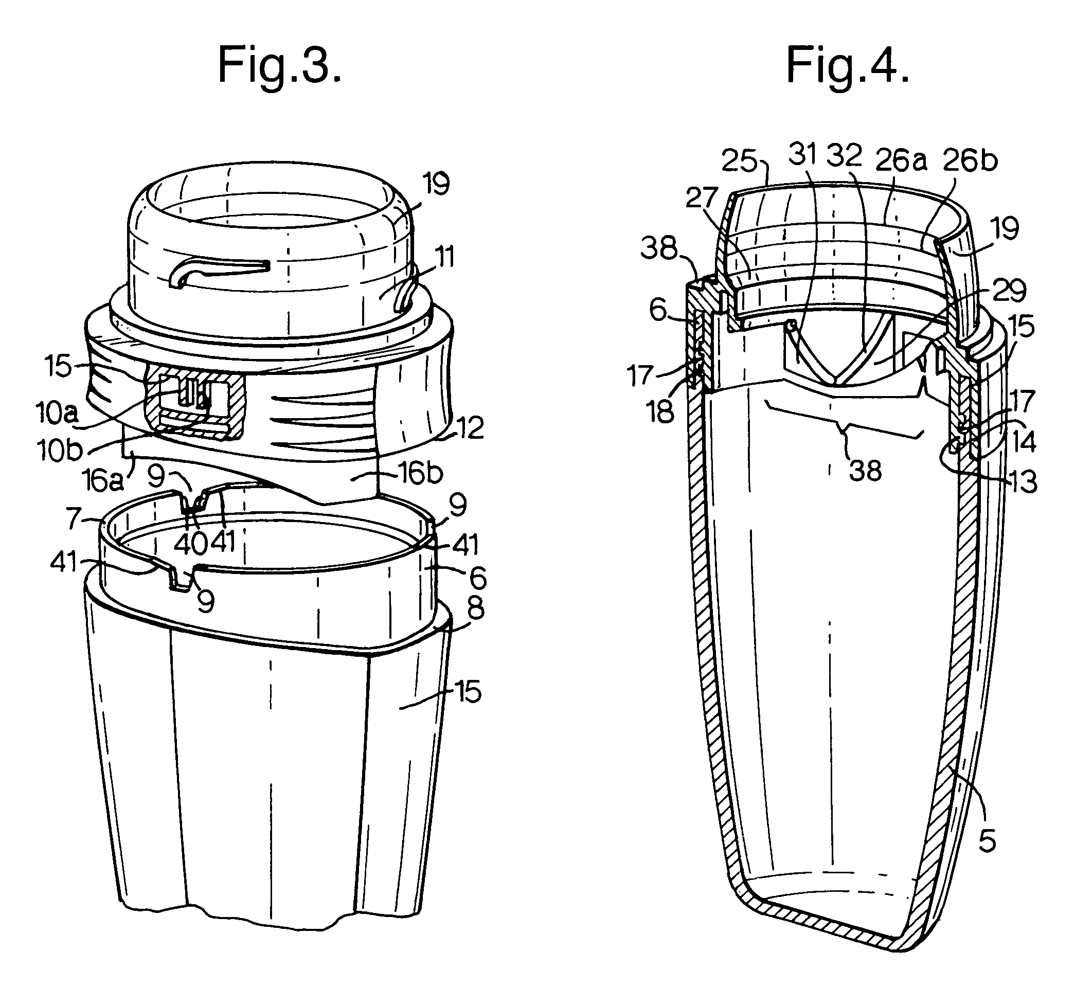
[0015]The present invention relates to solving problems associated with a dispenser having a bottle that is separately moulded from a housing for a flow regulator that is sealable by a cap that rotates around a common axis of cap and housing. When the cap is rotated around the housing, rotational forces are transmitted initially to the housing, and there is often a stop provided to prevent over-rotation of the cap. Impact on the stop can jar the housing, resulting, so it is believed in localised distortion which can facilitate the housing popping out of the mouth of the bottle. It is self-evident that mounting the cap on the bottle rather than on the housing inevitably requires the skirt of the cap to be lengthened completely over the housing and a sufficient overlap of the bottle side-wall for a securing means, in practice increasing the length of the skirt by at least 50% and maybe even doubling the length of the skirt. Consequently, such an option is seen as being less preferred ...


PUM


Abstract

In cosmetic dispensers for fluids, such as for example deodorants or antiperspirants comprising a bottle, a flow regulator in a housing mounted on the bottle and a cap rotatably mounted on the bottle or particularly onto the flow regulator housing, there is a risk that the housing can part from the bottle or be moved out of alignment by fitting or removal of the cap. This problem can be ameliorated or eliminated by employing a plurality of sets of anti-rotation elements at or adjacent to the mouth of the bottle around its periphery, each set comprising a peg and a socket. Preferably, the housing is bifurcated inward of the flow regulator, one wall extending within the bottle and the other wall extending out side the wall, and desirably the bottle wall is of reduced wall thickness in the overlap so that the exterior of the bottle surface and housing surface can be flush at their line of contact.

Description

[0001]The present invention relates to a fluid cosmetic dispenser and in particular to improvements or modifications to a cosmetic dispenser for a fluid comprising a bottle, a dispensing outlet and a cap.BACKGROUND TO THE PRESENT INVENTION[0002]Herein the term fluid indicates a material other than a gas which is capable of flowing without retaining its physical shape and accordingly excludes firm solids which retain their shape when subjected to mild pressure. The term includes liquids or creams which may be aqueous or anhydrous and flowable particulate solids. In particular, the present invention is directed to dispensers of a liquid of low viscosity.[0003]One class of dispensers for cosmetic, including deodorants and / or antiperspirants is commonly called roll-ons. Such dispensers comprise a bottle that acts as a reservoir for a cosmetic fluid, a fluid dispensing outlet integral with or mounted on the bottle comprising a housing within which a roller, commonly a ball and preferably...

Claims


Application Information

Patent Timeline
Patent Type & Authority Patents(United States)
IPC IPC(8): B43K23/08B43K7/10A45D34/04B67D7/74
CPCA45D34/04A45D34/041
Inventor BAINES, ROGER ANTHONYHAIGH, PAULPAY, PAUL NICHOLASTAVARES DA SILVA, REGINALDO ALEXANDRESOMERS, MARK GEOFFREY
Owner CONOPCO INC D B A UNILEVER
Learn More