
Luneberg dielectric lens and method of producing same

a dielectric lens and dielectric technology, applied in the field of dielectric lenses, can solve the problems of insufficient performance, such as antenna gain, for practical use, and use of dielectric lenses, and achieve the effect of excellent antenna characteristics

Inactive Publication Date: 2010-03-02
SUMITOMO ELECTRIC IND LTD
View PDF8 Cites 226 Cited by
  • Summary
  • Abstract
  • Description
  • Claims
  • Application Information

AI Technical Summary

Benefits of technology

The present invention provides a Luneberg dielectric lens with excellent antenna characteristics for practical use. The lens has a unique structure consisting of a center layer and multiple layers with varying ceramic content. The ceramic content per unit volume of the layers decreases from the center layer to the outermost layer, and the standard deviation of the apparent density of each layer is very low. The invention also provides a method for producing a series of foam moldings with varying ceramic content for use in the fabrication of the dielectric lens. The resulting moldings have different weights and densities, with a standard deviation of 0.5 mg or less and 0.1 g / cm3 or less.

Problems solved by technology

In reality, however, since a molded product in which the dielectric constant is continuously varied according to an ideal curve given by the equation (1) is difficult to obtain, a Luneberg dielectric lens is produced by combining a plurality of discrete layers having different dielectric constants.
However, the antenna using the dielectric lens disclosed in U. S. Patent Published Application No. 20040029985 is not enough to satisfy performance, such as antenna gain, for practical use.

Method used


Image

  • Luneberg dielectric lens and method of producing same
  • Luneberg dielectric lens and method of producing same
  • Luneberg dielectric lens and method of producing same

Examples


example 1

[0112]A dielectric lens having a diameter of 800 mm and composed of 13 layers was produced as shown in Table 3. In Table 3, “number of layers” indicates a total number of layers inclusive of a center layer and dome-shaped layers.

[0113]The dielectric constant ∈r of each layer of the dielectric lens should be adjusted on the basis of the above-described theoretical formula (1). Thus, the content of a ceramic material and the apparent density of a molding of the expanded beads of each layer were adjusted. For the purpose of adjusting the apparent density with high accuracy, two kinds of resin particles (Resin Particles 1-1 and 1-2) were prepared and were foamed and expanded by the dispersion method under various conditions to obtain seven kinds of expanded beads (Expanded Beads 1-1 to 1-7). The expanded beads were classified to obtain 13 kinds of expanded beads having varying apparent densities for the fabrication of the 13 layers of the dielectric lens. Details of the preparation of t...

example 2

[0129]A dielectric lens having a diameter of 370 mm and composed of 8 layers was produced as shown in Table 3. Two kinds of resin particles (Resin Particles 2-1 and 2-2) were prepared and were foamed and expanded by the dispersion method under various conditions to obtain six (6) kinds of expanded beads (Expanded Beads 2-1 to 2-6). The expanded beads were classified to obtain eight (8) kinds of expanded beads having varying apparent densities for the fabrication of the 8 layers of the dielectric lens. Detailed procedures are as follows.

Preparation of Resin Particles:

[0130]Resins (Resin 1 and Resin 3) shown in Table 1 and ceramic (Cer 2) shown in Table 2 were blended in the proportion shown in Table 7. Each blend was kneaded in a two-axis extruder, extruded and pelletized to obtain Resin Particles 2-1 and 2-2 in the form of columnar particles. The maleic anhydride contents of Resin Particles 2-1 and 2-2 are shown in Table 7.

[0131]

TABLE 7MaleicCeramicsanhydrideResinAmountPolypropylene...

example 3

[0139]A dielectric lens having a diameter of 450 mm and composed of 8 layers was produced as shown in Table 3. The same eight (8) kinds of expanded beads having varying apparent densities as used in Example 2 were used for the fabrication of the 8 layers of the dielectric lens in Example 3.

Preparation of Moldings of Expanded Beads:

[0140]Each of the 8 kinds of expanded beads were placed in a pressurized tank having an inside pressure shown in Table 10 for 48 hours so that the expanded beads had the same inside pressure as the inside pressure of the tank. The 8 kinds of the expanded beads having the increased inside pressure were filled in respective molds, to which steam having the pressure shown in Table 10 was fed for fuse-bonding the beads together. The molds were then cooled to obtain 8 moldings of the expanded beads. One of moldings was a hemispherical layer for use as the innermost, 1st layer of the dielectric lens, while the other moldings were hemispherical dome-like shells f...


PUM

PropertyMeasurementUnit
apparent densityaaaaaaaaaa
lengthaaaaaaaaaa
diameteraaaaaaaaaa

Abstract

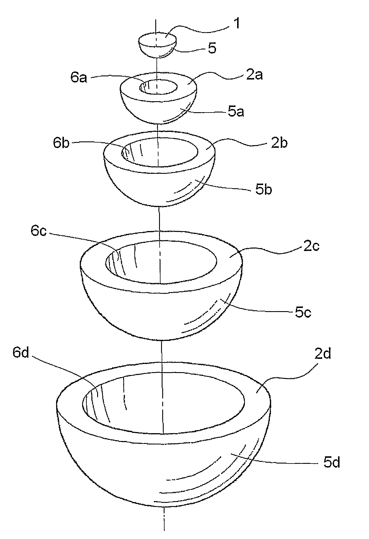
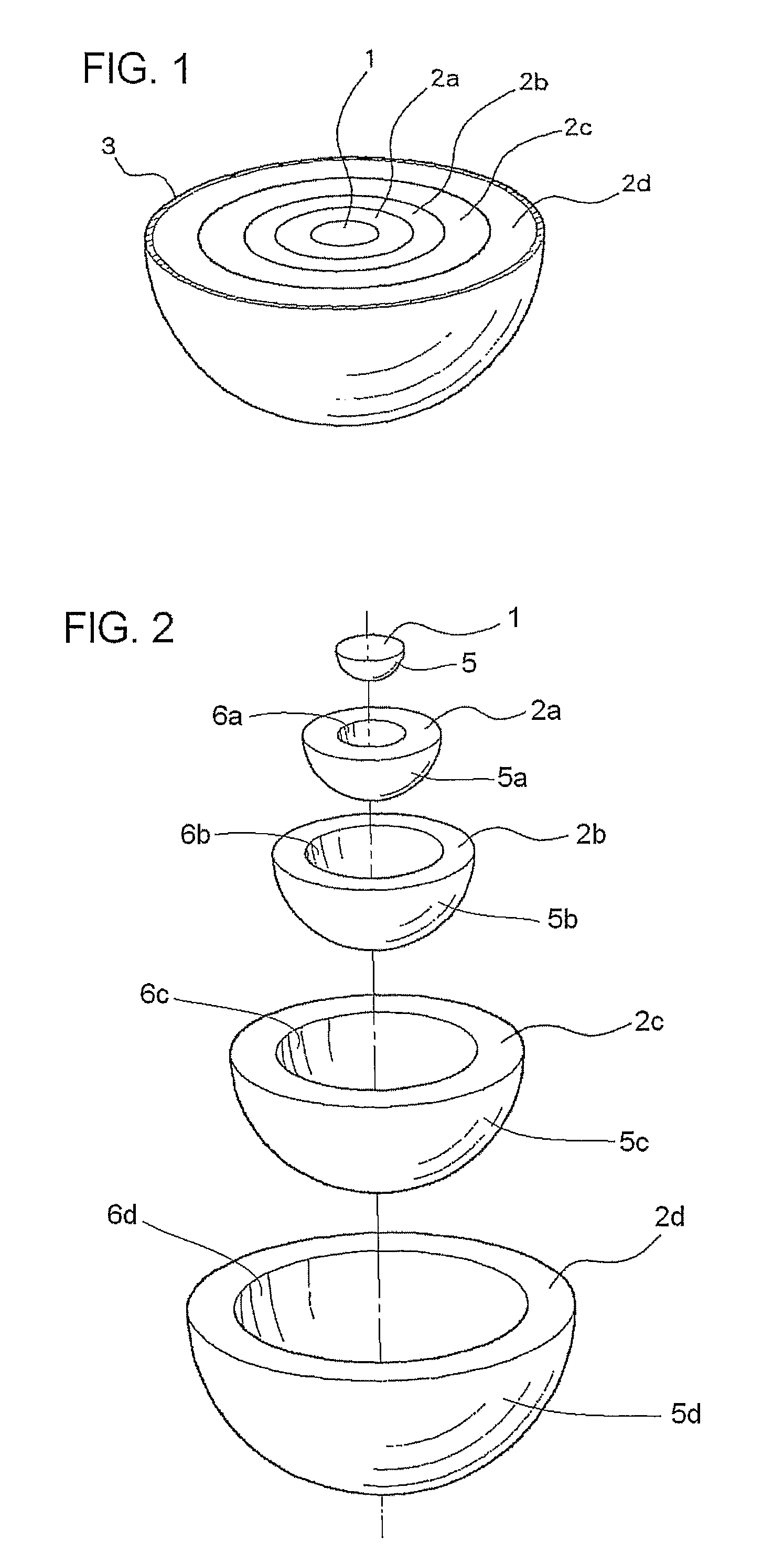
A hemispherical Luneberg dielectric lens including a hemispherical center layer having a hemispherical outer surface, and a plurality of hemispherical dome-shaped layers each having concentric hemispherical inner and outer surfaces, the outer surfaces of the center layer and dome-shaped layers having different diameters and the inner surfaces of said dome-shaped layers having different diameters. The center layer and dome-shaped layers are successively concentrically fitted into one another and integrated into a hemispherical shape. The center layer is a foam molding of ceramic-containing thermoplastic resin expanded beads, while each of said dome-shaped layers is a foam molding of thermoplastic resin expanded beads containing 0 to 80% by weight of a ceramic. The ceramic content per unit volume of the center and dome-shaped layers decreases from the center layer to the outermost dome-shaped layer, and the standard deviation of the apparent density of each of the center and dome-shaped layers is 0.07 g / cm3 or lower.

Description

RELATED APPLICATIONS[0001]This application is the U.S. National Phase under 35 U.S.C. § 371 of International Application No. PCT / JP2005 / 016987, filed on Sep. 8, 2005, which in turn claims the benefit of Japanese Application No. 2004-264109, filed on Sep. 10, 2004, the disclosures of which Applications are incorporated by reference herein.TECHNICAL FIELD[0002]This invention relates to a dielectric lens. More specifically, the present invention relates to a hemispherical Luneberg dielectric lens in which a hemispherical, ceramic-containing foam center layer and a plurality of hemispherical, dome-shaped foam layers are concentrically stacked and in which the ceramic content per unit volume of each layer is adjusted. The present invention is also directed to a method of producing a series of foam moldings for use in fabrication of a dielectric lens.BACKGROUND ART[0003]With the remarkable development of information communication technology and increase of the amount of information in rec...

Claims


Application Information

Patent Timeline
Patent Type & Authority Patents(United States)
IPC IPC(8): H01Q25/00
CPCC04B38/06H01Q15/08H01Q19/062C04B14/4637C04B26/02C04B2111/00939
Inventor TOKORO, HISAOSASAKI, KAZUTOSHISHINOHARA, MITSURUSAKAGUCHI, MASAKAZUKURODA, MASATOSHIKIMURA, KOICHIISHIBASHI, YOSHIYUKI
Owner SUMITOMO ELECTRIC IND LTD
Learn More