Rotary clip rotation for air gun

a technology of rotation mechanism and air gun, which is applied in the direction of compressed gas guns, white arms/cold weapons, safety arrangements, etc., can solve the problems of affecting the durability of the gun, the mechanism of rotating the rotary clip, and the rotary clip itself, so as to suppress degradation and damage to the nail, improve durability, and reduce the effect of deterioration

Active Publication Date: 2010-03-02
MARUZEN
View PDF7 Cites 17 Cited by
  • Summary
  • Abstract
  • Description
  • Claims
  • Application Information

AI Technical Summary

Benefits of technology

[0025]According to the present invention, a rotary clip rotation mechanism is constructed of a hard member such as metal, which means that there is no need to consider temperature and air pressure at the time of molding, and design of members constituting the rotary clip rotation mechanism, and selection of materials and quality control, are easy.
[0026]A nail, being a movable member for rotating the rotary clip, has linear reciprocating movement without moving in an arc shape, as in related art 2, which means that in the event that a space in which the nail can move is widened to the same extent as in related art 2, it is possible to make the nail and respective members of the rotary clip rotation mechanism larger. As a result it is possible to suppress degradation and damage to the nail, and durability is improved compared to related art 2.

Problems solved by technology

A rotary clip loaded into the air gun body is rotated by a rotation member for rotating the rotary clip, but there are occasions where a situation arises where it becomes impossible to rotate the rotary clip due to a bullet remaining between the bore of the rotary clip and the barrel, etc.
In this type of situation, if an attempt is made to force the rotary clip to rotate, there is a danger of the mechanism for rotating the rotary clip, or the rotary clip itself, being damaged.
However, related art 1 has a simple structure, but synthetic resin such as plastic constituting the material has molding conditions that are easily changed according to temperature and air pressure, and there is a problem in that design of members constituting the rotary clip rotation mechanism, and selection of material and quality control, are difficult.
Therefore, if the rotary clip is rotated for a long period of time with a small nail, the likelihood of degradation or damage to sections such as the nail is high, and there is a problem that the whole of the rotary clip rotation mechanism lacks durability.

Method used


Image

  • Rotary clip rotation for air gun
  • Rotary clip rotation for air gun
  • Rotary clip rotation for air gun

Examples


Embodiment Construction

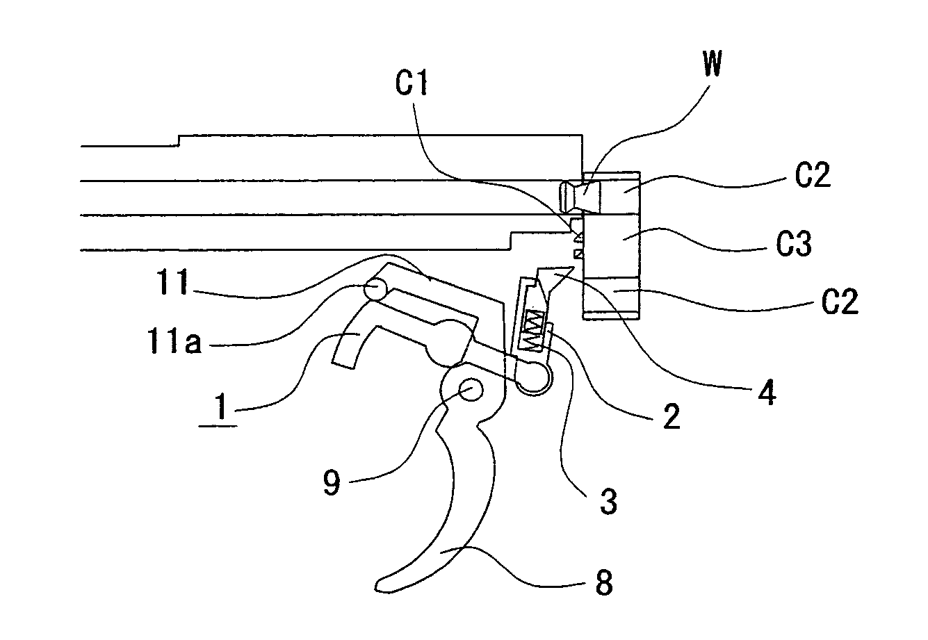
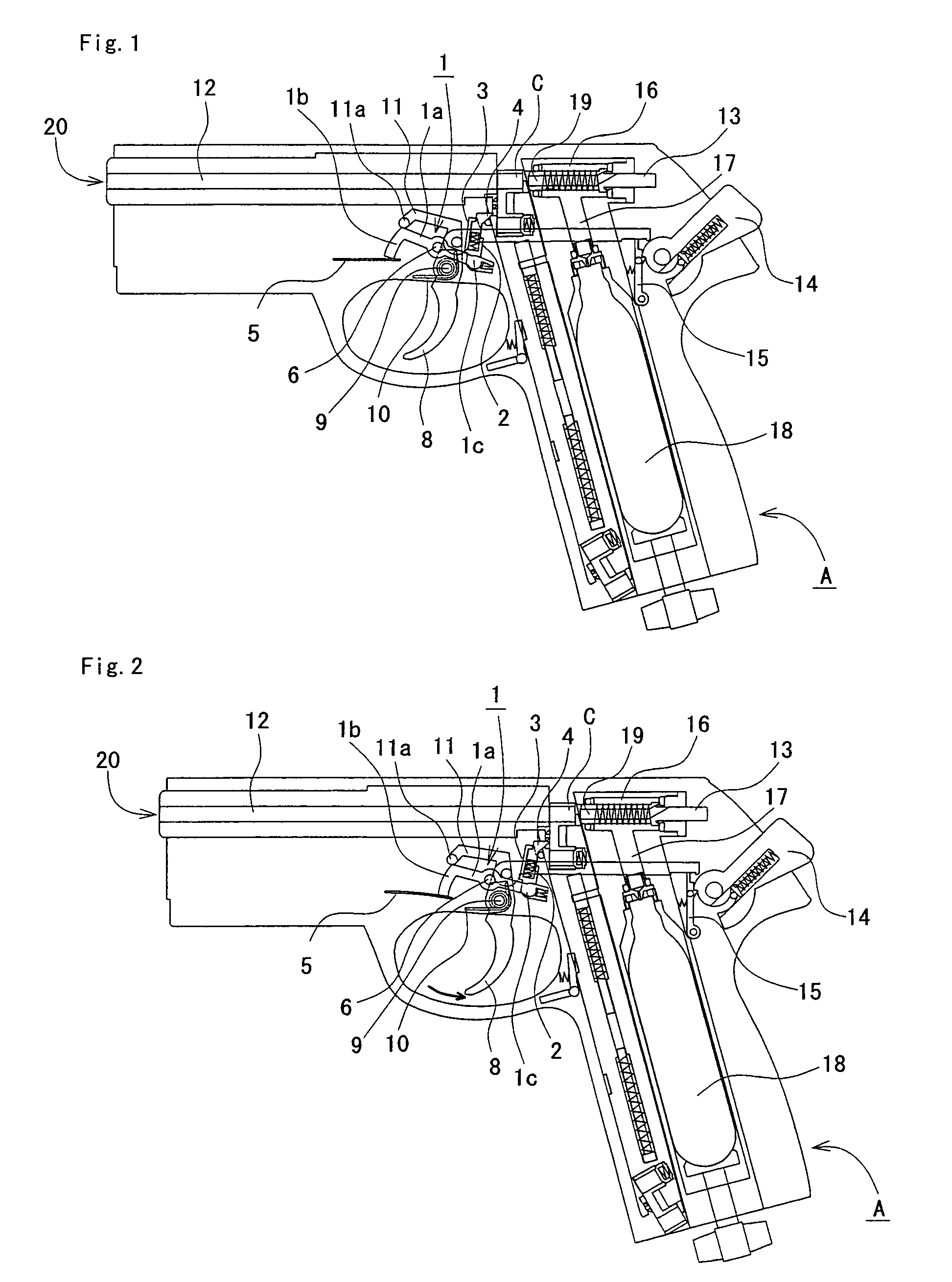
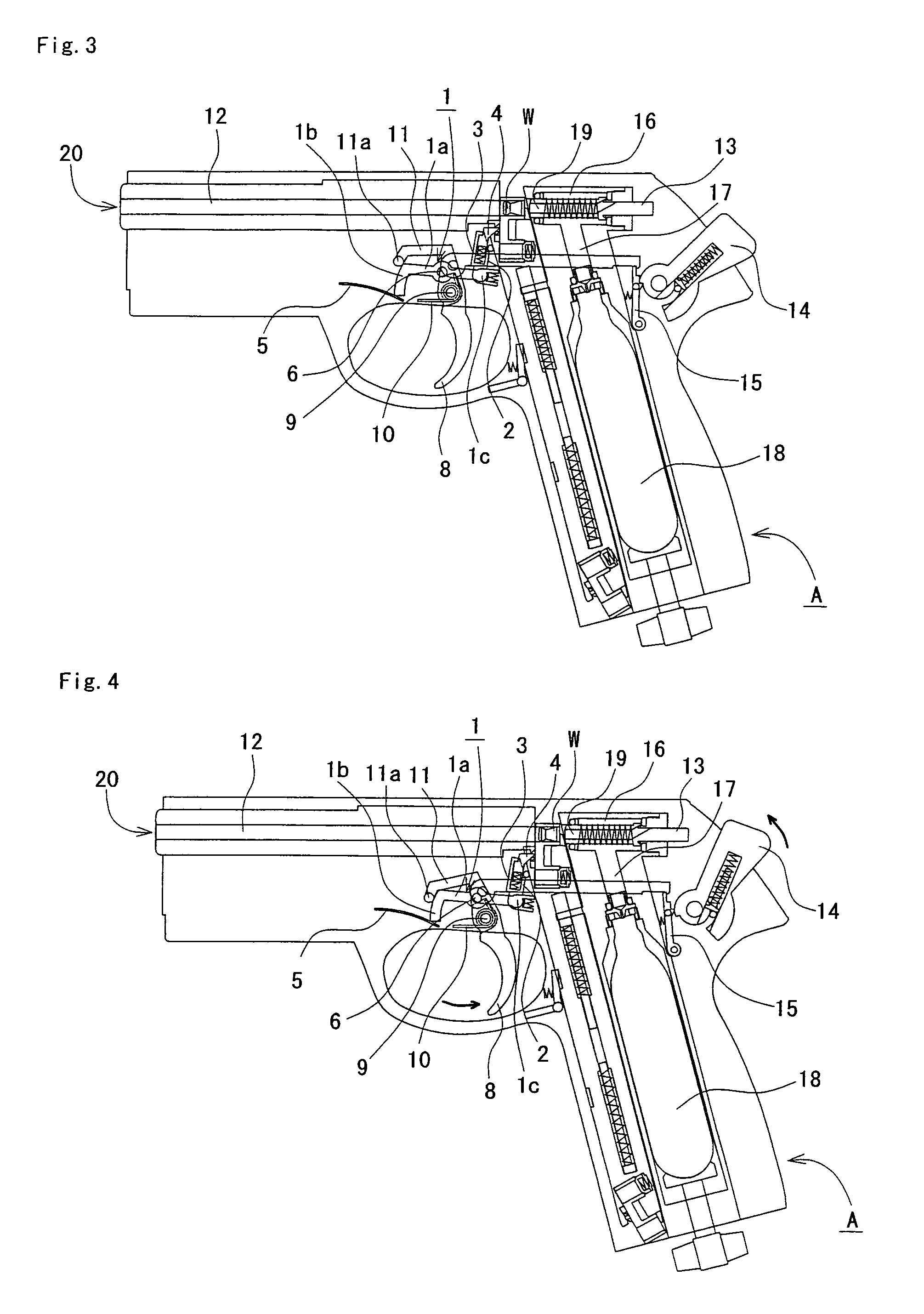
[0043]For a rotary clip rotation mechanism for an air gun of an embodiment of the present invention, FIG. 1 to FIG. 5 show normal operation at the time of successfully rotating a rotary clip. FIG. 1 is a central cross-sectional explanatory drawing of an air gun showing, in a rotary clip rotation mechanism of an air gun of an embodiment of the present invention, a state where a hammer is moved to the gun rear end side and bullets can be fired by pulling the trigger, FIG. 2 is a central cross-sectional explanatory drawing of an air gun showing a state immediately after pulling a trigger from FIG. 1, FIG. 3 is a central cross-sectional explanatory drawing of an air gun showing a state immediately after pulling a trigger further back than FIG. 2, FIG. 4 is a central cross-sectional drawing of an air gun showing a state after FIG. 3, where a hammer starts to advance, and FIG. 5 is a central cross-sectional drawing of an air gun showing a state, after FIG. 4, immediately after firing a bu...


PUM


Abstract

A rotary clip rotation mechanism for an air gun, having a nail for engaging with a nail engagement section provided in the rotary clip and causing rotation of a rotary clip, comprises an L-shaped arm, capable of rotating about an arm shaft, with a muzzle side end opening section formed from a curved surface section; an arm elastic section provided at a position contacting the tip of the curved surface section of the L-shaped arm, a nail support arm provided so as to rotate on a gun rear end side of the L-shaped arm by means of a connecting elastic section, and a nail urged in the direction of the tip end by a nail elastic section provided on a tip of the nail support arm.

Description

BACKGROUND OF THE INVENTION[0001]1. Field of the Invention[0002]This invention relates to a rotary clip (rotary cylinder, rotary magazine) rotation mechanism for an air gun.[0003]2. Description of the Related Art[0004]As shown in FIG. 11, a rotary clip of an air gun is provided with 6 to 8 circular bores (bullet containment sections) capable of being loaded with a single bullet of BB shot or pellet shot, and the bores are rotated to continuously fire bullets.[0005]Generally, an air gun rotary clip is provided at one or both ends of a substantially rectangular solid shaped magazine body of a magazine, and this magazine is loaded by inserting into a magazine holding section formed from a cavity in the air gun body.[0006]A magazine that has been inserted into the magazine holding section is ejected from the magazine holding section once all bullets contained in the rotary clip bores have been fired, and after reloading the empty bores with bullets it is fitted into the magazine holding...

Claims


Application Information

Patent Timeline
Patent Type & Authority Patents(United States)
IPC IPC(8): F41B11/00F41B11/54
CPCF41B11/54
Inventor MAEDA, TETSUO
Owner MARUZEN
Why Eureka
Try Eureka