
Computer method and apparatus for representing a topic in a software modeling system

Active Publication Date: 2010-02-23
INT BUSINESS MASCH CORP
View PDF7 Cites 23 Cited by
  • Summary
  • Abstract
  • Description
  • Claims
  • Application Information

AI Technical Summary

Benefits of technology

This approach ensures that diagrams remain synchronized with the underlying model automatically, reducing the risk of conflicts and simplifying team collaboration by eliminating the need for manual updates and persisting notation data.

Problems solved by technology

The problem is that the core knowledge of what the topic the diagram is trying to represent resides in the user's mind.
Any time that information is persisted to a common file, introduces issues in a team development environment that is under source control (source files are checked into a source control system such as CVS or ClearCase).
Team members can concurrently make edits to the common file which can precipitate conflicts and resulting merges when the edits are checked in to the source control system.

Method used


Image

  • Computer method and apparatus for representing a topic in a software modeling system
  • Computer method and apparatus for representing a topic in a software modeling system
  • Computer method and apparatus for representing a topic in a software modeling system

Examples


Embodiment Construction

[0015]A description of preferred embodiments of the invention follows.

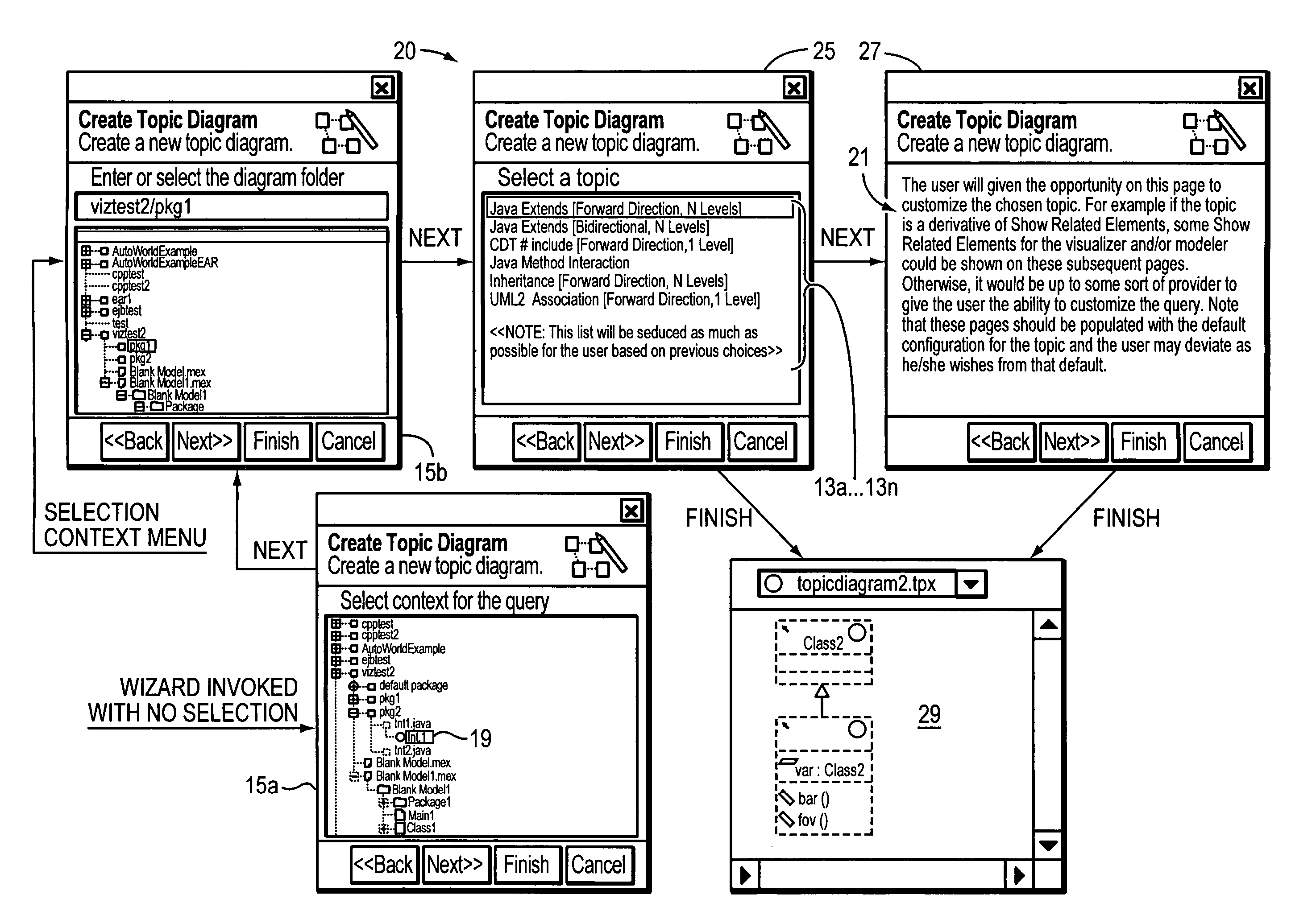
[0016]Applicants' approach is to consider the original problem (e.g., a diagram that represents the inheritance tree of a particular class) and then conceptualize the diagram as a “topic”, i.e., expand by n with constraint of relationship . This is all the information the user needs in order to manually generate the diagram and save the diagram notation elements. As used herein, “notation elements” are the data objects that store information about how to display underlying semantic elements (UML2). For example, this information includes size, position, color, etc. However, if this information in the form of a “topic” query is all that is needed to generate the diagram, why is it necessary to persist the diagram notation elements? As noted above, persisting the diagram notation elements can cause issues with check-in conflicts that are sometimes difficult to resolve. If the diagram has knowledge of the query in an...


PUM


Abstract

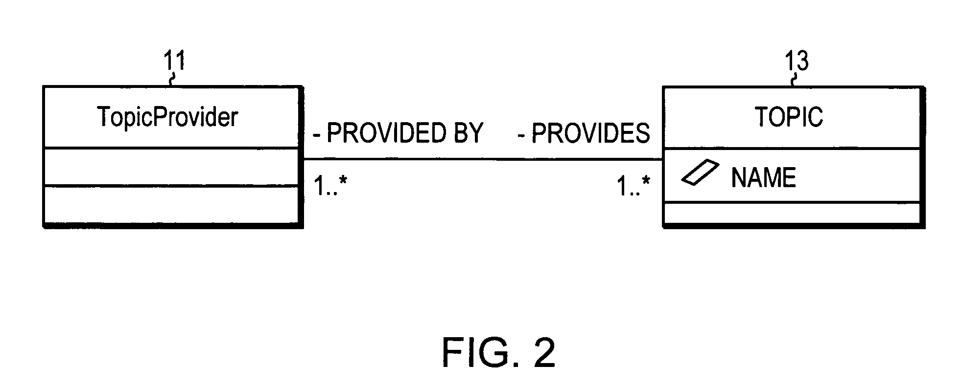
A computer method and apparatus for visual modeling software programs represents a topic by providing a respective topic diagram. The topic diagram is non-editable and has non-persisting notation data. The topic diagram demonstrates a respective set of relationships between one or more given elements representative of the subject topic. The topic diagram is derived based on a query which saves search criteria and information that enables an editor to generate the diagram notation data. There are different topic providers for different queries. A topic service manages the topic providers and processes client calls (requests) regarding specific context and query. Queries are end-user customizable and are extensible per topic.

Description

BACKGROUND OF THE INVENTION[0001]In the software industry, designing of software programs typically begins with a modeling stage of the subject system. The UML is a visual modeling language (with formal syntax and semantics) for communicating a model or conceptualization. The UML syntax enables software designers to express (specify and document) the subject problems and solutions in a standardized manner. The UML semantics enable knowledge about the subject system to be captured and leveraged during the problem solving phase.[0002]In that light, in UML or modeling languages generally, diagrams can be described as a graphical view on some semantic data. They are used to visualize the data in a way that is understandable to the user. An example is the UML class diagram. A diagram's purpose is to convey some specific aspect or topic about the data it is displaying. Typically the user describes this topic when he is creating the diagram using a tool. Briefly, diagramming tools are used...

Claims


Application Information

Patent Timeline
Patent Type & Authority Patents(United States)
IPC IPC(8): G06F3/048
CPCG06F8/10
Inventor CHAFE, STEPHANIE L.LEROUX, DANIEL D.MCGEE, CHRISTIE B.SHAW, STEVEN R.
Owner INT BUSINESS MASCH CORP
Learn More