
Dispenser

a technology for dispensers and containers, applied in the field of dispensers, can solve the problems of cling wraps that are difficult to flatten out, the holder is quite large, and the adhesive is too large,

Inactive Publication Date: 2010-02-23
BECKER ELIZABETH FREDERICKA +1
View PDF3 Cites 22 Cited by
  • Summary
  • Abstract
  • Description
  • Claims
  • Application Information

AI Technical Summary

Benefits of technology

"The invention is a dispenser for cling wrap that includes a paper core that can rotate within the dispenser, a handle, and a stop to hold the core in place. The handle is made of paper or cardboard and acts as a stop to prevent the roll from moving too far away from the end. The dispenser also includes a protective layer around the handle. The invention also includes a combination of the dispenser and a roll of cling wrap, where the core is mounted on the dispenser and held in place by secondary stop means. The technical effects of this invention include improved handling and stability of the cling wrap, making it easier to use and transport."

Problems solved by technology

Cling wrap is a particularly satisfactory form of wrapping material having the ability to adhere to itself so that it can easily be wrapped around an article to be covered, However a disadvantage of cling wrap is that it will adhere to itself even when it is not intended that it should do so, and in particular if it folds or creases and it is often difficult thereafter to flatten out the cling wrap for use.
Although this works quite satisfactorily, the cost of the holder is quite significant and this makes the cost of the entire product less attractive.

Method used


Image

  • Dispenser
  • Dispenser
  • Dispenser

Examples


Embodiment Construction

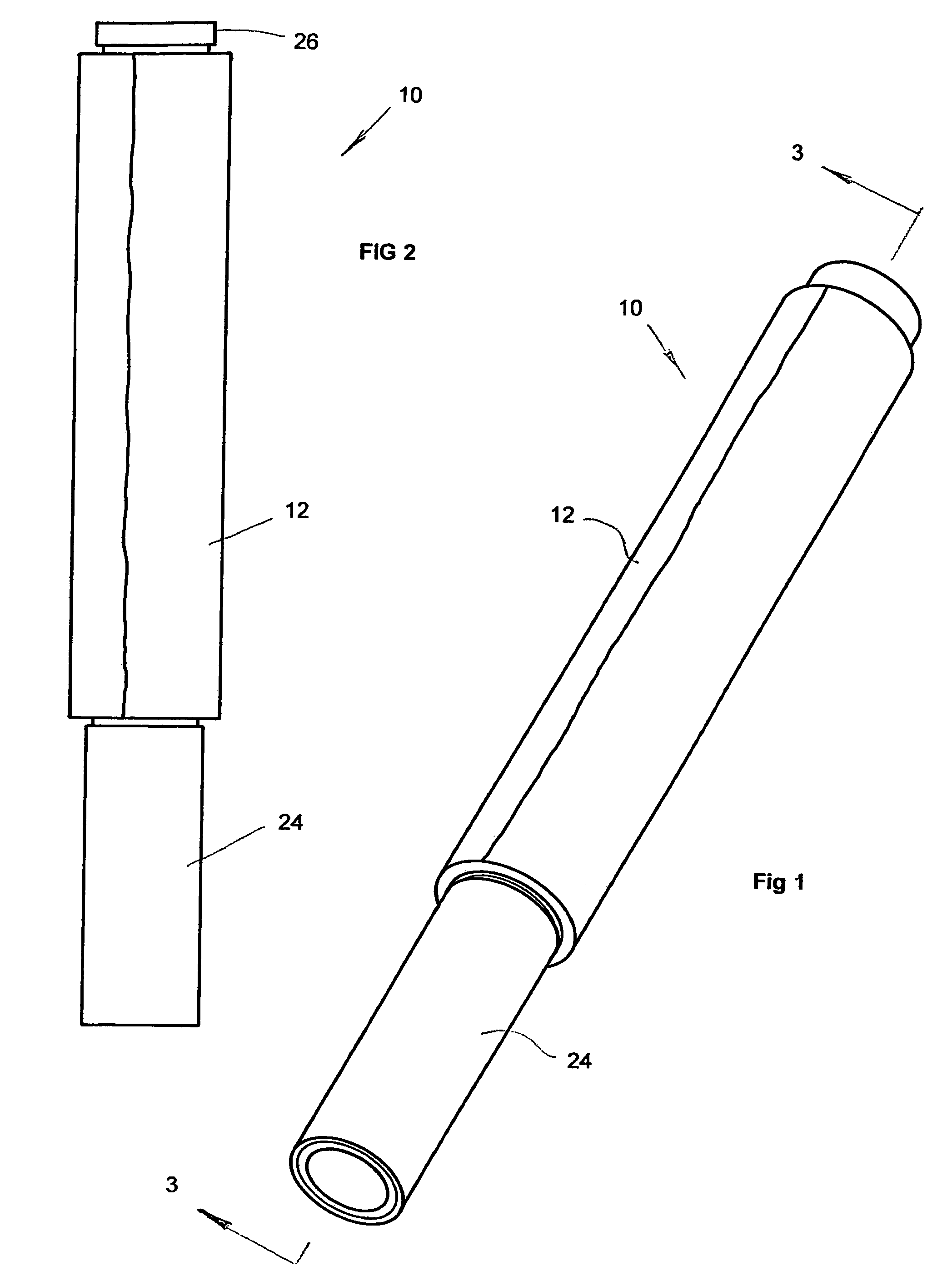
[0017]Referring now to the drawings there is shown a dispenser 10 for use in dispensing cling wrap from a roll 12 that is wound around a wound paper core 14 (hereinafter called the “wrap core”).

[0018]The dispenser 10 comprises an elongated hollow wound paper core 16. The axial length of the dispenser core 16 can be and preferably is longer than the wrap core 14. It comprises a spindle portion 18, a handle portion 20 on one side thereof and a short end portion 22 on the other end thereof.

[0019]The outside diameter of the dispenser core 16 is slightly less than the inside diameter of the wrap core 14 so that there is annular space therebetween. The spindle portion 18 defines a round cylindrical shaft which fits in the wrap core 14 which can now rotate thereabout,

[0020]Fitted on to the handle portion 20 is a handle liner 24 preferably in the form of a wound paper core. The inside diameter of the handle liner 24 is only slightly greater than the outside diameter of the dispenser core 16...


PUM

PropertyMeasurementUnit
lengthaaaaaaaaaa
lengthaaaaaaaaaa
diameteraaaaaaaaaa

Abstract

A dispenser is described for a roll of cling wrap wound on a paper core (the “wrap core’), The dispenser comprises a main paper core which fits in the wrap core in such a way that the wrap core can rotate thereabout. A handle portion in the form of a paper core is wrapped around the main core on one side of the wrap core and a stop member formed of the same paper core is wrapped around the end section. The wrap core is held in position between the handle section arid the stop member. When the cling wrap has been fully used, the user disposes of the dispenser.

Description

CROSS-REFERENCE TO RELATED APPLICATIONS[0001]PRIORITY CLAIM: 35 U.S.C. 119(a) Pursuant to 35 U.S.C. 119(a), this application claims the priority of South African Patent Application No. 2005 / 01143, filed on Feb. 7, 2005.FIELD OF THE INVENTION[0002]This invention relates to dispensers for a thin plastic wrapping material known as cling wrap or shrink wrap film (the term “cling wrap” will be used for this material in this specification).BACKGROUND OF THE INVENTION[0003]Cling wrap is sold in a roll wrapped around a hollow core (the “wrap core”). One form of cling wrap which is available in the United States is sold under the name Saran Wrap, which is polyvinylidene chloride film produced by The Dow Chemical Company. Cling wrap is a particularly satisfactory form of wrapping material having the ability to adhere to itself so that it can easily be wrapped around an article to be covered, However a disadvantage of cling wrap is that it will adhere to itself even when it is not intended tha...

Claims


Application Information

Patent Timeline
Patent Type & Authority Patents(United States)
IPC IPC(8): B65H49/00
CPCB65H16/04B65H2701/1752
Inventor BECKER, ELIZABETH FREDERICKAVAN WYK, BEVERLY GAIL
Owner BECKER ELIZABETH FREDERICKA
Learn More