
Method and system for inter-fabric routing

a technology of inter-fabric routing and routing methods, applied in the field of fibre channel network systems, can solve the problem that the switch device must accommodate new devices

Active Publication Date: 2010-02-09
MARVELL ASIA PTE LTD
View PDF6 Cites 16 Cited by
  • Summary
  • Abstract
  • Description
  • Claims
  • Application Information

AI Technical Summary

Benefits of technology

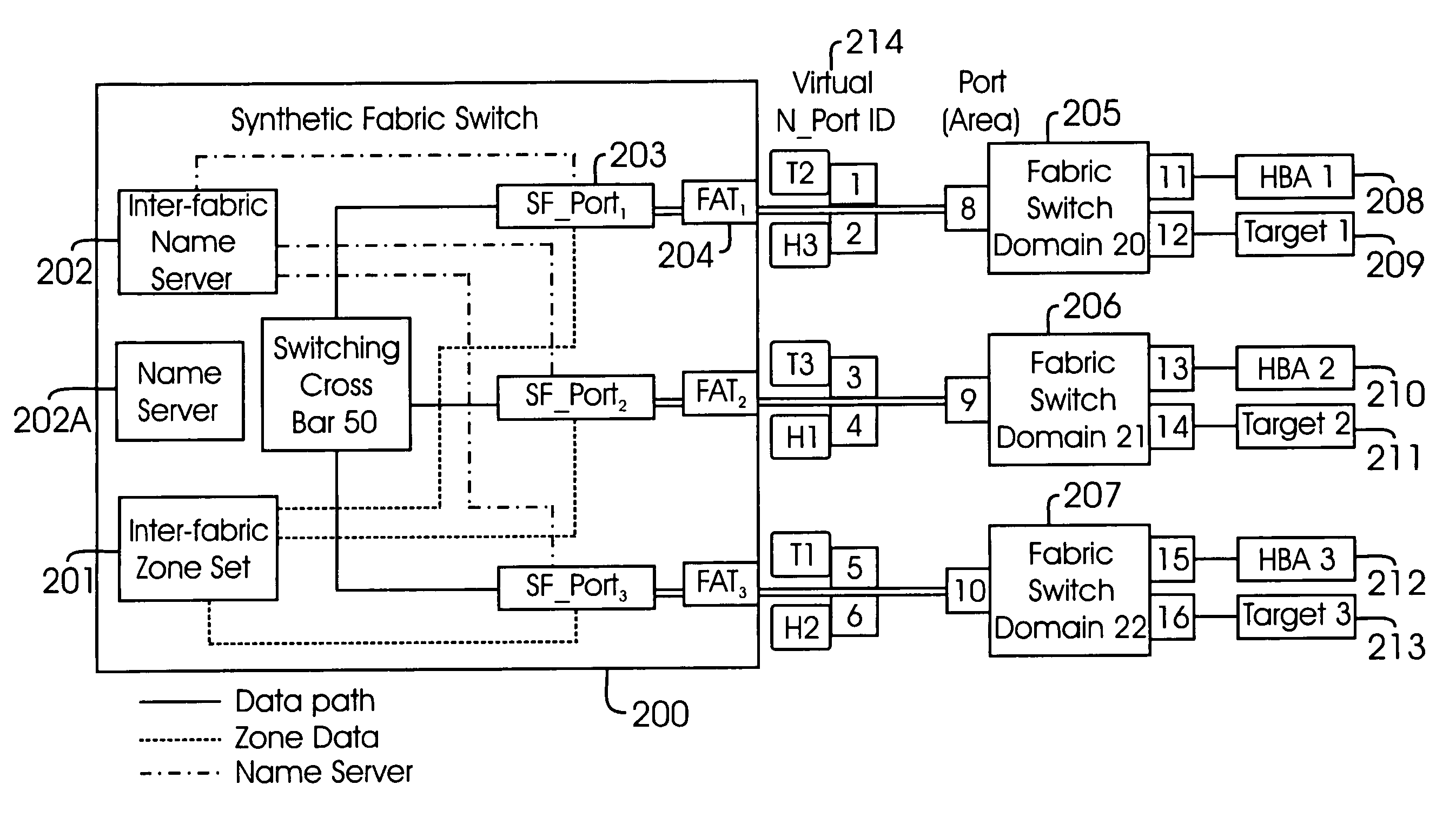
The present invention provides a Fibre Channel switch element that allows for routing Inter-Fabric frames without using Inter-Fabric frame headers. This is achieved by using a switch port with a world wide port number that is used in a specific zone set. The invention also provides a network comprising at least two Fabrics coupled to a host system and a target device, and a method for routing Inter-Fabric frames using the switch element. The technical effects of the invention include improved efficiency and reliability in routing Inter-Fabric frames and reduced latency in data transfer.

Problems solved by technology

The use of SAN islands has been common because switch suppliers have forced limits on SAN size and Information Technology managers have been reluctant to build larger SANs due to concerns about fault containment.
One disadvantage of this approach is that switch devices have to accommodate new header types, new Fabric routing protocols and extensions.

Method used


Image

  • Method and system for inter-fabric routing
  • Method and system for inter-fabric routing
  • Method and system for inter-fabric routing

Examples


Embodiment Construction

Definitions

[0026]The following definitions are provided for convenience as they are typically (but not exclusively) used in the Fibre Channel environment, implementing the various adaptive aspects of the present invention.

[0027]“CRC” (cyclic redundancy code): A 4 byte value used for checking data integrity of a Fibre Channel frame.

[0028]“D_ID”: A 24-bit Fibre Channel header field that contains the destination address for a frame.

[0029]“E_Port”: An expansion port that is used to connect Fibre Channel Switch elements in a Fabric.

[0030]“Fabric”: The structure or organization of a group of switches, target and host devices (NL_Port, N_ports etc.).

[0031]“Fabric Tag”: An identifier assigned to each Fabric and it's value is set to the port number of the SF_Port that has a native connection to the Fabric.

[0032]“FAT”: Fabric Address Translator that monitors incoming frames, compares D_ID and S_ID values, and when a match is found, replaces the D_ID and S_ID values with those contained within...


PUM


Abstract

A Fibre Channel Switch element and method for Inter-Fabric routing is provided. The switch element includes a switch port whose worldwide port number is used in a zone set to enable Inter-Fabric frame routing without using Inter-Fabric frame headers. The method includes querying a Name Server to determine world wide port numbers of devices; storing query results in an Inter-Fabric Name Server module; extracting world wide port numbers for each switch port; registering Proxy Devices with the Name Server, wherein the Proxy Devices interface with the switch ports as if it was they were actual devices to route Inter-Fabric frames; and establishing Fabric Address Translator entries so that source identification values and destination identification values are mapped to route Inter-Fabric frames without using Inter-Fabric frame headers.

Description

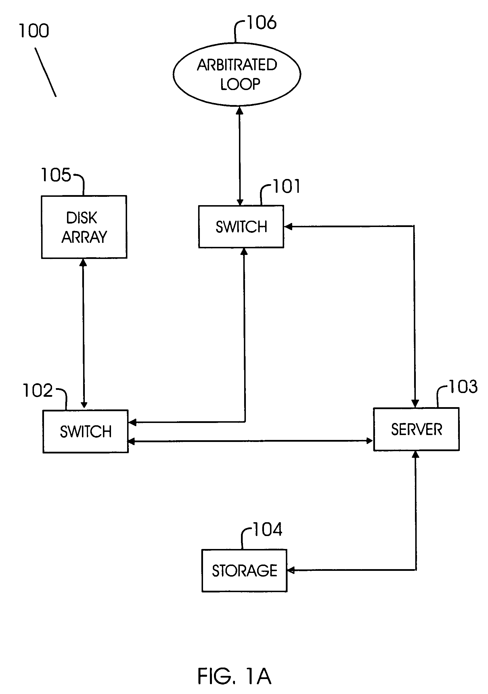
BACKGROUND[0001]1. Field of the Invention[0002]The present invention relates to Fibre Channel network systems, and more particularly, to Inter-Fabric routing.[0003]2. Background of the Invention[0004]Fibre Channel is a set of American National Standard Institute (ANSI) standards, which provide a serial transmission protocol for storage and network protocols such as HIPPI, SCSI, IP, ATM and others. Fibre Channel provides an input / output interface to meet the requirements of both channel and network users.[0005]Fibre Channel supports three different topologies: point-to-point, arbitrated loop and Fibre Channel Fabric. The point-to-point topology attaches two devices directly. The arbitrated loop topology attaches devices in a loop. The Fibre Channel Fabric topology attaches host systems directly to a Fabric, which are then connected to multiple devices. The Fibre Channel Fabric topology allows several media types to be interconnected.[0006]Fibre Channel Fabric devices include a node p...

Claims


Application Information

Patent Timeline
Patent Type & Authority Patents(United States)
IPC IPC(8): H04L12/28H04L12/56
CPCH04L47/10H04L47/29H04L49/357H04L49/3009H04L49/351
Inventor MCGLAUGHLIN, EDWARD C
Owner MARVELL ASIA PTE LTD
Learn More