Surface protection film-attached optical film and image display

a technology of surface protection film and optical film, applied in the direction of cellulosic plastic layer products, instruments, polarising elements, etc., can solve the problems of static electricity generation, non-existent problems, antistatic agents can bleed out and stain the attached material, etc., to reduce the amount of peeling electrostatic charge

Inactive Publication Date: 2010-02-09
NITTO DENKO CORP
View PDF21 Cites 13 Cited by
  • Summary
  • Abstract
  • Description
  • Claims
  • Application Information

AI Technical Summary

Benefits of technology

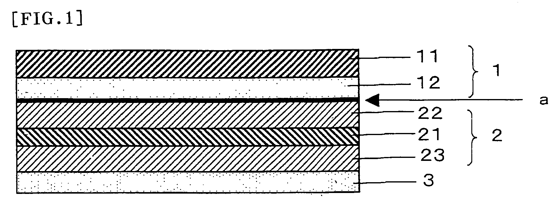
[0006]It is an object of the invention to provide a surface protection film-attached optical film that includes an optical film and a surface protection film provided on the surface of the optical film, can reduce the amount of peeling electrostatic charge which can be generated when the surface protection film is peeled off from the optical film, and can be free from the problem of optical film surface contamination after the surface protection film is peeled off.
[0014]The ionic antistatic agent contained in the pressure-sensitive adhesive layer of the surface protection film can be transferred from the surface of the pressure-sensitive adhesive layer to the surface of the optical film so that peeling electrostatic charge can be prevented when the surface protection film is peeled off and that static electricity-induced defects can be prevented. If the amount of the antistatic agent added to the pressure-sensitive adhesive is increased, the antistatic agent can also bleed out from the pressure-sensitive adhesive in addition to the amount of the initially transferred antistatic agent so that the antistatic effect can be increased. However, if the amount of the transferred antistatic agent (the bleeding-out amount) becomes too large, the surface of the optical film can be significantly stained so that defective optical properties can be generated. Such an amount of the transferred antistatic agent can also cause changes or a reduction in adhesion. If the amount of the antistatic agent added to the pressure-sensitive adhesive is too small, the antistatic effect cannot be sufficiently obtained, although there will be no problem of contamination or any contamination can easily be controlled.
[0015]According to the invention, the pressure-sensitive adhesive layer of the surface protection film contains the antistatic agent, and the surface of the optical film is activated by treatment, so that a proper amount of the antistatic agent can be transferred even in the case where the amount of the antistatic agent added to the pressure-sensitive adhesive layer is relatively small. According to the invention, therefore, a proper amount of the antistatic agent can be efficiently transferred so that the potential contamination of the surface of the optical film can be controlled while the antistatic effect is imparted to the surface of the optical film. The amount of transfer of the antistatic agent can also be regulated so that changes or a reduction in adhesion can also be suppressed.

Problems solved by technology

Therefore, the surface protection film has a problem in which when it is peeled off, static electricity can be generated to destroy a circuit of an LCD panel or the like.
It also has another problem in which it can have an influence on an array element (TFT driving element) inside an LCD panel, which can further have an influence on the liquid crystal orientation to induce defects.
Such problems can occur not only when the surface protection film is peeled off but also when friction occurs between optical films by a manufacturing process or customer's operation.
However, the pressure-sensitive adhesive tape has a problem in which the antistatic agent can bleed out to stain the attached material.
Since optical films are particularly sensitive to surface contamination, such a pressure-sensitive adhesive tape cannot be applied to surface protection films for use in optical films.

Method used


Image

  • Surface protection film-attached optical film and image display
  • Surface protection film-attached optical film and image display

Examples


example 1

[0097]The antiglare layer side of the polarizing plate prepared in Comparative Example 1 was subjected to saponification treatment by dipping the side in an aqueous 10% sodium hydroxide solution at 65° C. for 30 seconds. The surface protection film prepared in Comparative Example 2 was used. A surface protection film-attached optical film was prepared by attaching the pressure-sensitive adhesive layer side of the surface protection film to the antiglare layer side of the polarizing plate.

example 2

[0098]The antiglare layer side of the polarizing plate prepared in Comparative Example 1 was subjected to saponification treatment by dipping the side in an aqueous 10% sodium hydroxide solution at 65° C. for 120 seconds. The surface protection film prepared in Comparative Example 2 was used. A surface protection film-attached optical film was prepared by attaching the pressure-sensitive adhesive layer side of the surface protection film to the antiglare layer side of the polarizing plate.

example 3

[0099]The antiglare layer side of the polarizing plate prepared in Comparative Example 1 was corona-treated at 0.7 kW and a line speed of 5 m / minute. The surface protection film prepared in Comparative Example 2 was used. A surface protection film-attached optical film was prepared by attaching the pressure-sensitive adhesive layer side of the surface protection film to the antiglare layer side of the polarizing plate.


PUM

PropertyMeasurementUnit
thicknessaaaaaaaaaa
thicknessaaaaaaaaaa
thicknessaaaaaaaaaa

Abstract

A surface protection film-attached optical film of the invention comprises: an optical film; and a surface protection film that comprises a substrate film and a pressure-sensitive adhesive layer and is provided on the surface of, the optical film through the pressure-sensitive adhesive layer, wherein a surface of the optical film in contact with the pressure-sensitive adhesive layer is activated by treatment, and the pressure-sensitive adhesive layer of the surface protection film contains an ionic antistatic agent. The surface protection film-attached optical film can reduce the amount of peeling electrostatic charge which can be generated when the surface protection film is peeled off from the optical film, and can be free from the problem of optical film surface contamination after the surface protection film is peeled off.

Description

TECHNICAL FIELD[0001]The invention relates to a surface protection film-attached optical film that includes an optical film and a protection film provided on the surface of the optical film. The invention also relates to an image display using the surface protection film-attached optical film, such as a liquid crystal display, an organic electro-luminescent display, and a plasma display panel. The optical film may be a polarizing plate, a retardation plate, an optical compensation film, a brightness enhancement film, a laminate thereof, or the like.BACKGROUND ART[0002]The image-forming mode of liquid crystal displays or the like requires polarizing elements to be placed on both sides of a liquid crystal cell, and generally polarizing plates are attached thereto. Besides polarizing plates, a variety of optical elements have been used for liquid crystal panels to improve display quality. For example, there are used retardation plates for prevention of coloring, viewing angle expansion...

Claims


Application Information

Patent Timeline
Patent Type & Authority Patents(United States)
IPC IPC(8): B32B7/12C09J201/00B32B7/02C09J7/02G02B5/30G02B1/10G02F1/1335G02F1/13363
CPCB32B7/12G02B1/16B32B23/08B32B23/20B32B27/306B32B27/36G02B1/14G02B1/105G02F1/13363G02F2202/22B32B2307/21B32B2307/412B32B2307/42B32B2307/516B32B2457/20Y10T428/273Y10T428/28
Inventor SATAKE, MASAYUKISHIRAFUJI, FUMIAKI
Owner NITTO DENKO CORP
Why Eureka
Try Eureka