
Hole saw having efficient slug removal

a technology of slug removal and hole saw, which is applied in the field of hole saws, can solve the problems of affecting the performance of the turning machine, the difficulty of removing the hole slug, and the major challenge of the removal of the slug, and achieve the effect of reducing frictional engagemen

Inactive Publication Date: 2010-02-09
CAPPYS CONCEPTS
View PDF36 Cites 50 Cited by
  • Summary
  • Abstract
  • Description
  • Claims
  • Application Information

AI Technical Summary

Benefits of technology

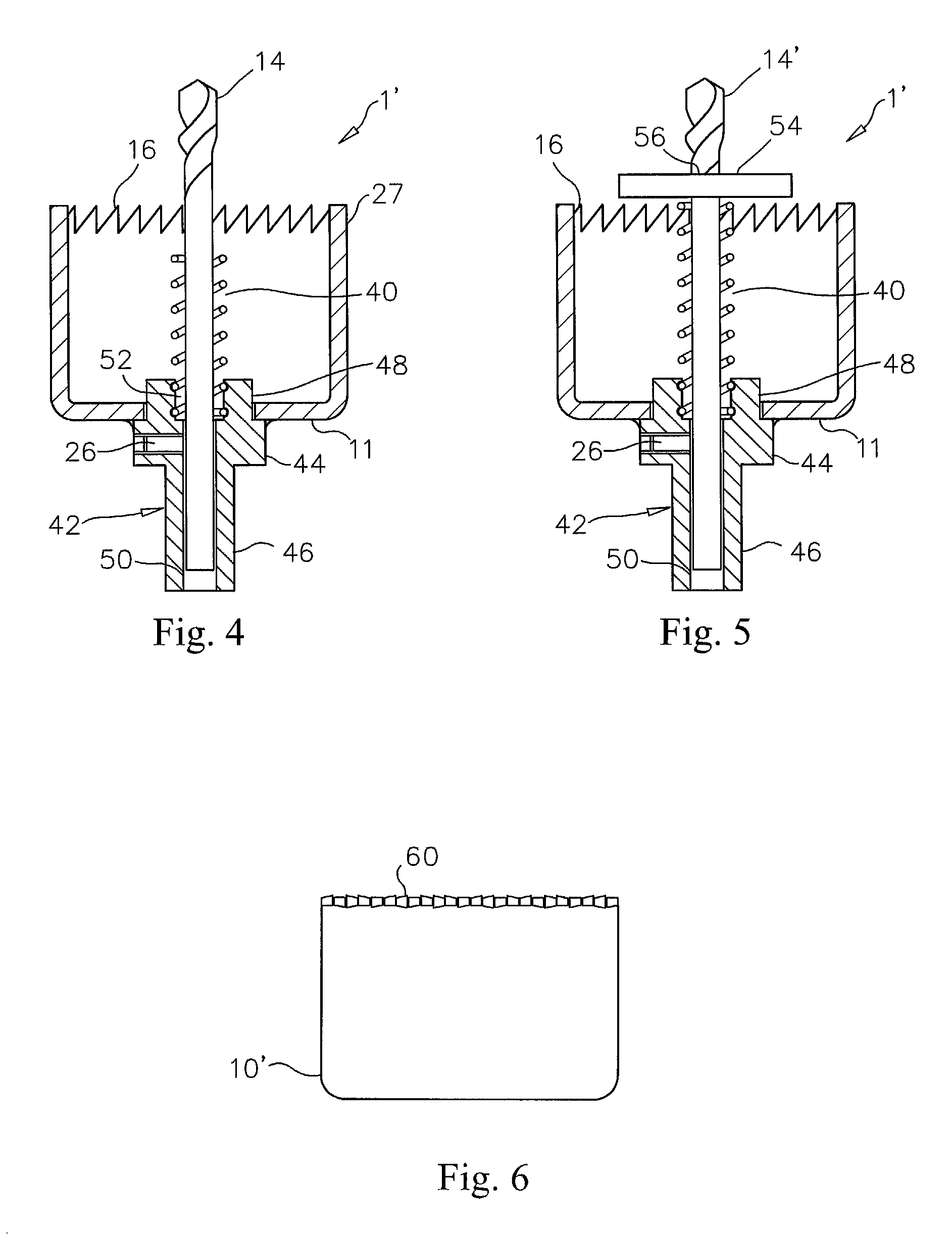
[0010]The shank portion is attached to the closed end of the saw cup with any suitable fastening process. The pilot cutting device is preferably a drill, but other cutting devices may also be used. A shank opening is formed through the shank portion to receive the shank of the pilot cutting device. Preferably, a threaded fastener, such as a set screw is used to retain the pilot cutting device in the shank opening. A compression spring may be retained in the shank portion to provide extra help to remove a slug. A contact disc may be placed between the pilot cutting device and the compression spring to evenly distribute force from the compression spring against the slug.
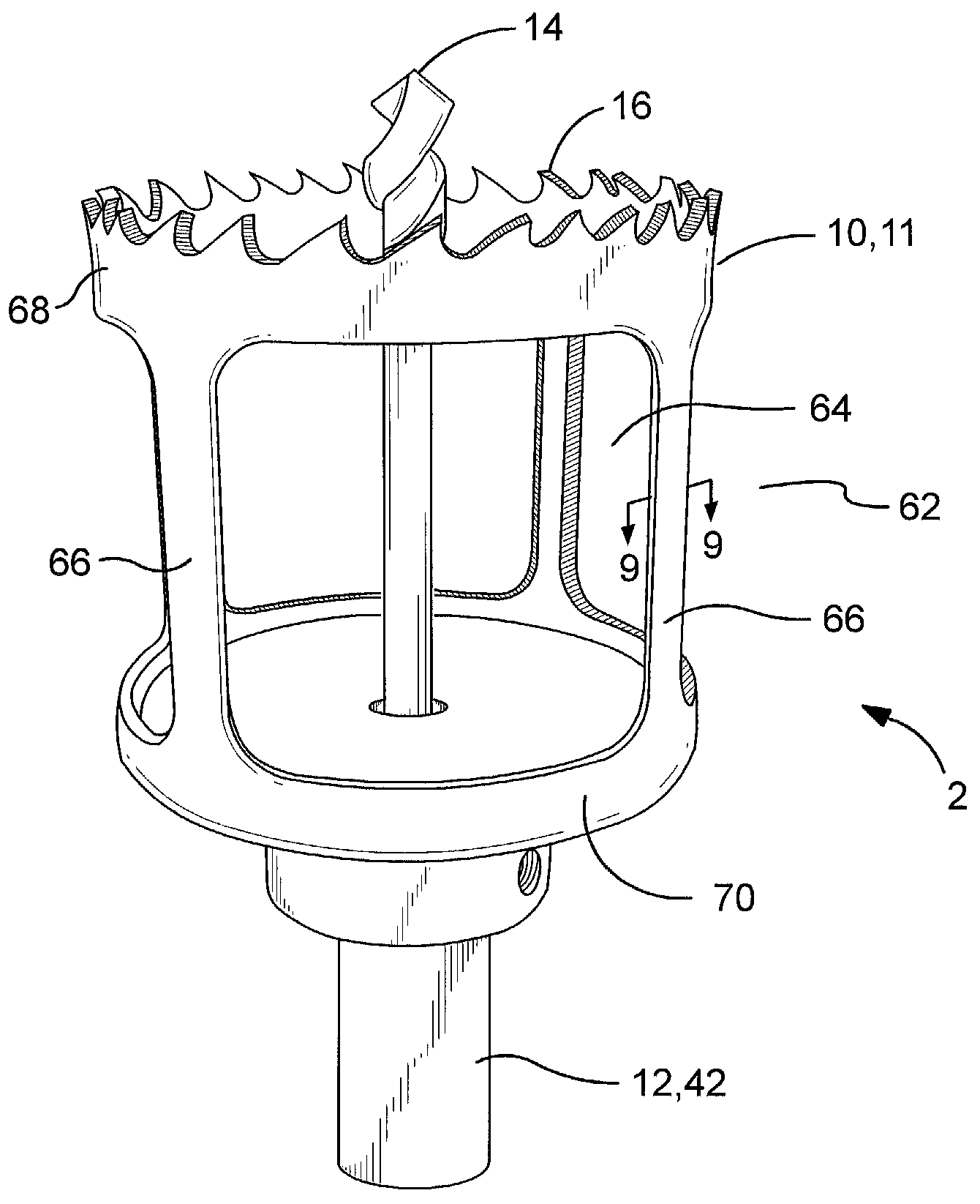
[0012]Accordingly, it is an object of the present invention to provide a saw cup with a substantial portion of a side wall removed to decrease frictional engagement with the hole created and a slug generated by the saw cup.

Problems solved by technology

However, an aggravating problem encountered with hole saws is the removal of a hole slug from the cup.
Depending upon the material of the hole slug, removal of the slug can be a major challenge.
However, neither the cylindrical body of the hole saw or the cutting teeth are coated with teflon.

Method used


Image

  • Hole saw having efficient slug removal
  • Hole saw having efficient slug removal
  • Hole saw having efficient slug removal

Examples


Embodiment Construction

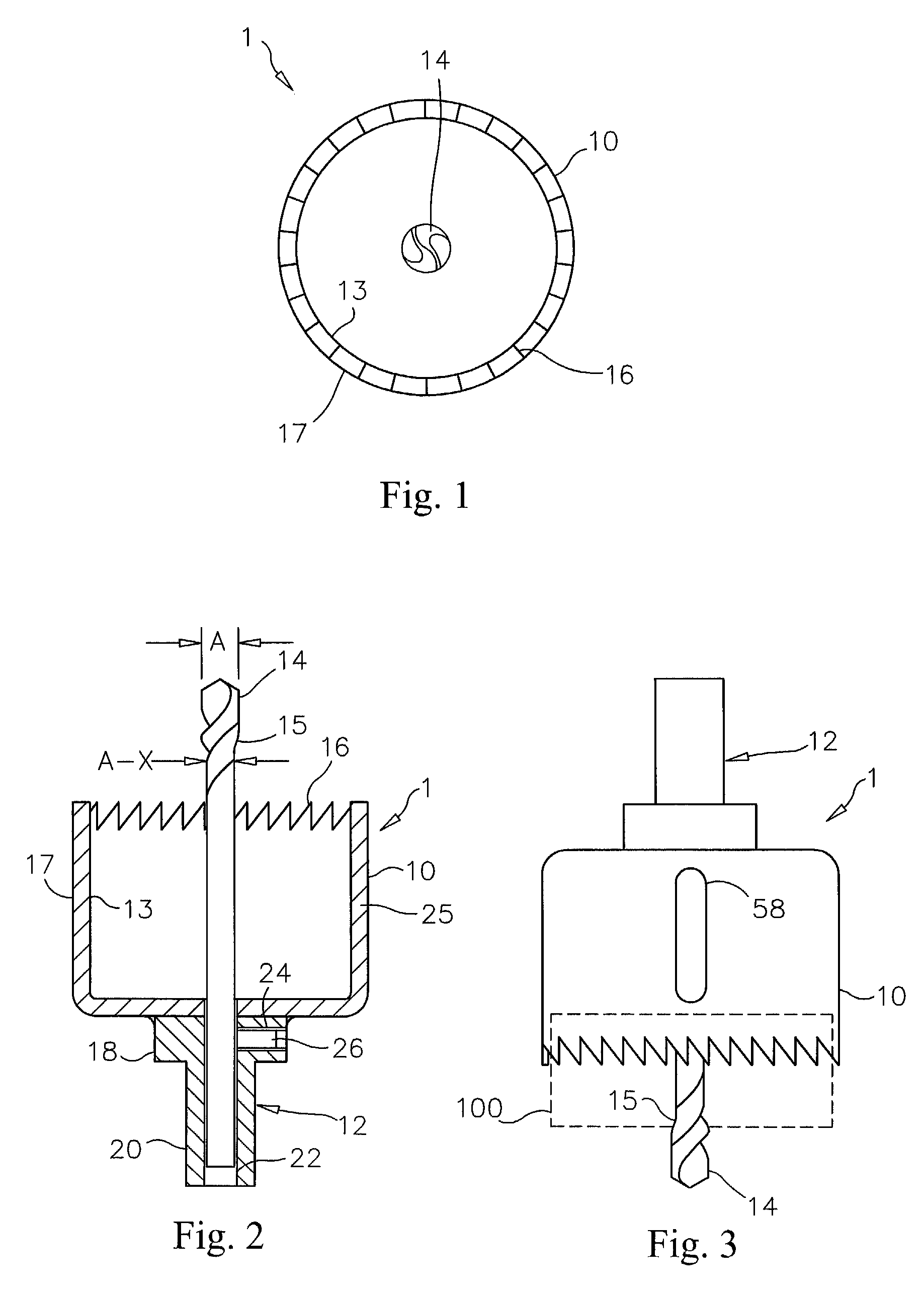
[0023]With reference now to the drawings, and particularly to FIG. 1, there is shown a bottom end view of a hole saw having efficient slug removal 1. With reference to FIG. 2, the hole saw having efficient slug removal 1 includes a saw cup 10, a shank portion 12 and a pilot cutting device, such as a location drill 14. The shank portion 12 is attached to a closed end of the saw cup 10 with any suitable fastening process, such as welding. A plurality of cutting teeth 16 are formed on an open end of the saw cup 10.

[0024]An inside surface 13 of the saw cup 10 extending from a tip of the cutting teeth 16 to substantially the closed end of the saw cup 10 is given a low friction treatment. An outside surface 17 of the saw cup 10 extending from a tip of the cutting teeth 16 to substantially a closed end of the saw cup 10 is also preferably given a low friction treatment. The low friction treatment preferably includes applying a low friction coating to a surface and baking the low friction c...


PUM

PropertyMeasurementUnit
Fractionaaaaaaaaaa
Diameteraaaaaaaaaa
Widthaaaaaaaaaa

Abstract

A hole saw having efficient slug removal preferably includes a saw cup, a shank portion and a pilot cutting device. A cutting surface is formed on an open end of the saw cup. An inside surface of the saw cup is given a low friction treatment and preferably an outside surface thereof. The shank portion is retained on a closed end of the saw cup. The pilot cutting device is preferably a drill, but other cutting devices may also be used. A second embodiment of a hole saw having efficient slug removal preferably includes a saw cup, a shank portion and a pilot cutting device. The saw cup includes a prior art saw cup, at least two side openings and a cutting surface. The at least two side openings are formed through the prior art saw cup to remove a substantial portion of a side wall.

Description

CROSS-REFERENCES TO RELATED APPLICATIONS[0001]This is a continuation-in-part patent application taking priority from nonprovisional application Ser. No. 11 / 832,970 filed on Aug. 2, 2007, which takes priority from nonprovisional application Ser. No. 11 / 511,709 filed on Aug. 29, 2006.BACKGROUND OF THE INVENTION[0002]1. Field of the Invention[0003]The present invention relates generally to hole saws and more specifically to a hole saw having efficient slug removal, which allows a slug to be removed from the hole saw without the use of additional tools.[0004]2. Discussion of the Prior Art[0005]The most common type of hole saw is a cup with teeth formed on an open end, a shank attached to the other end of the cup, and a drill retained in the shank. The drill starts the hole cutting process by providing a pivotal anchor for cutting the hole with the cup. However, an aggravating problem encountered with hole saws is the removal of a hole slug from the cup. Depending upon the material of th...

Claims


Application Information

Patent Timeline
IPC IPC(8): B23B51/04
CPCB23B51/0453B23B2228/10Y10T408/51Y10T408/895Y10T408/8957Y10S408/703
Inventor BUZDUM, MIRKOCAPSTRAN, RICHARD E.
Owner CAPPYS CONCEPTS
Learn More