
Wireless signal transmission device for a DC brushless ceiling fan motor

a technology of wireless signal transmission and ceiling fan motor, which is applied in the direction of motor/generator/converter stopper, dynamo-electric converter control, instruments, etc., can solve the problems of inconvenient production, affecting the durability of components, and difficulty in ensuring the reliability of components, so as to ensure the rigidity and strength of the fan components. the effect of not being compromised

Inactive Publication Date: 2010-02-02
RHINE ELECTRONICS
View PDF6 Cites 2 Cited by
  • Summary
  • Abstract
  • Description
  • Claims
  • Application Information

AI Technical Summary

Benefits of technology

"The present invention provides a DC brushless ceiling fan motor with a wireless signal transmission device. The motor has a signal-transmitting device installed on top and a signal receiving device installed on the ceiling fan. The signal-transmitting device detects the position of the motor and sends a wireless signal to the signal receiving device, which then sends the signal to the motor to control its rotation. This eliminates the need to drill a hole in the fan body and ensures the strength and rigidity of the components are not compromised. The wireless signal transmission device also has primary and secondary windings that interact with a magnetic unit to create an electric current and supply power to the device. This simplifies the wiring structure of the fan."

Problems solved by technology

1. Destructive process is required: In order to place the signal transmission wire between the sensor and the controlling device, it is necessary to drill a hole on the body of the fan, allowing the signal transmission wire can be passed through the hole and connected to the controlling device. This process is destructive to the components of the fan, and may cause inconvenience and difficulty during production.
2. Damage to the strength and rigidity of the components: The hole required to allow the signal transmission wire to pass through and connect with the controlling device could compromise the rigidity and strength of the spindle of the motor, affecting the durability of the components.

Method used


Image

  • Wireless signal transmission device for a DC brushless ceiling fan motor
  • Wireless signal transmission device for a DC brushless ceiling fan motor
  • Wireless signal transmission device for a DC brushless ceiling fan motor

Examples


Embodiment Construction

[0020]While this invention is capable of embodiment in many different forms, shown in the drawings and herein described in detail is the preferred embodiment of the invention. The preferred embodiment in disclosed with the understanding that the present description is but one example of the principles of the invention and is not intended to limit the broad aspects of the invention to the single embodiment illustrated.

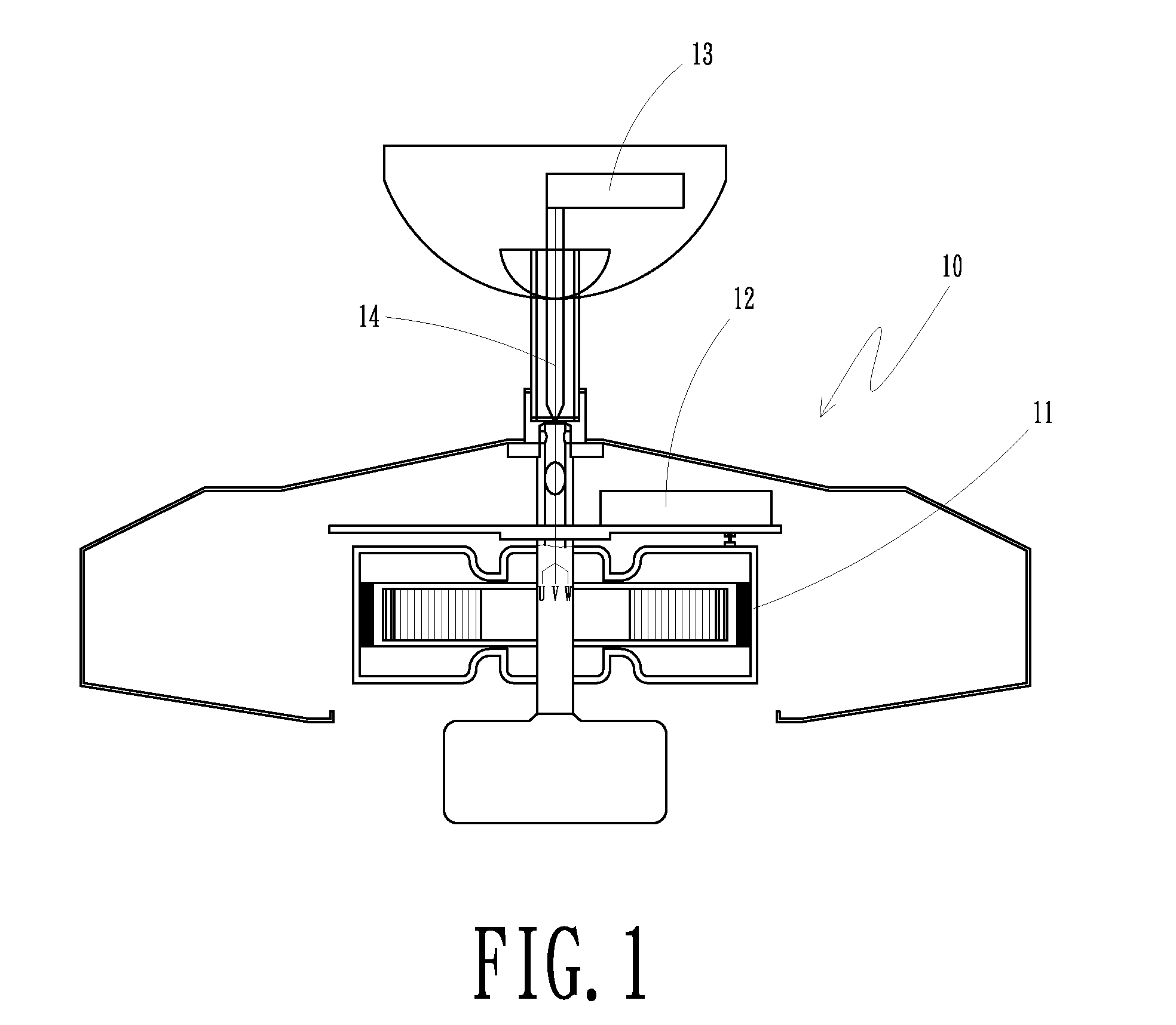
[0021]In reference to FIG. 1 through FIG. 3, the present invention comprises:

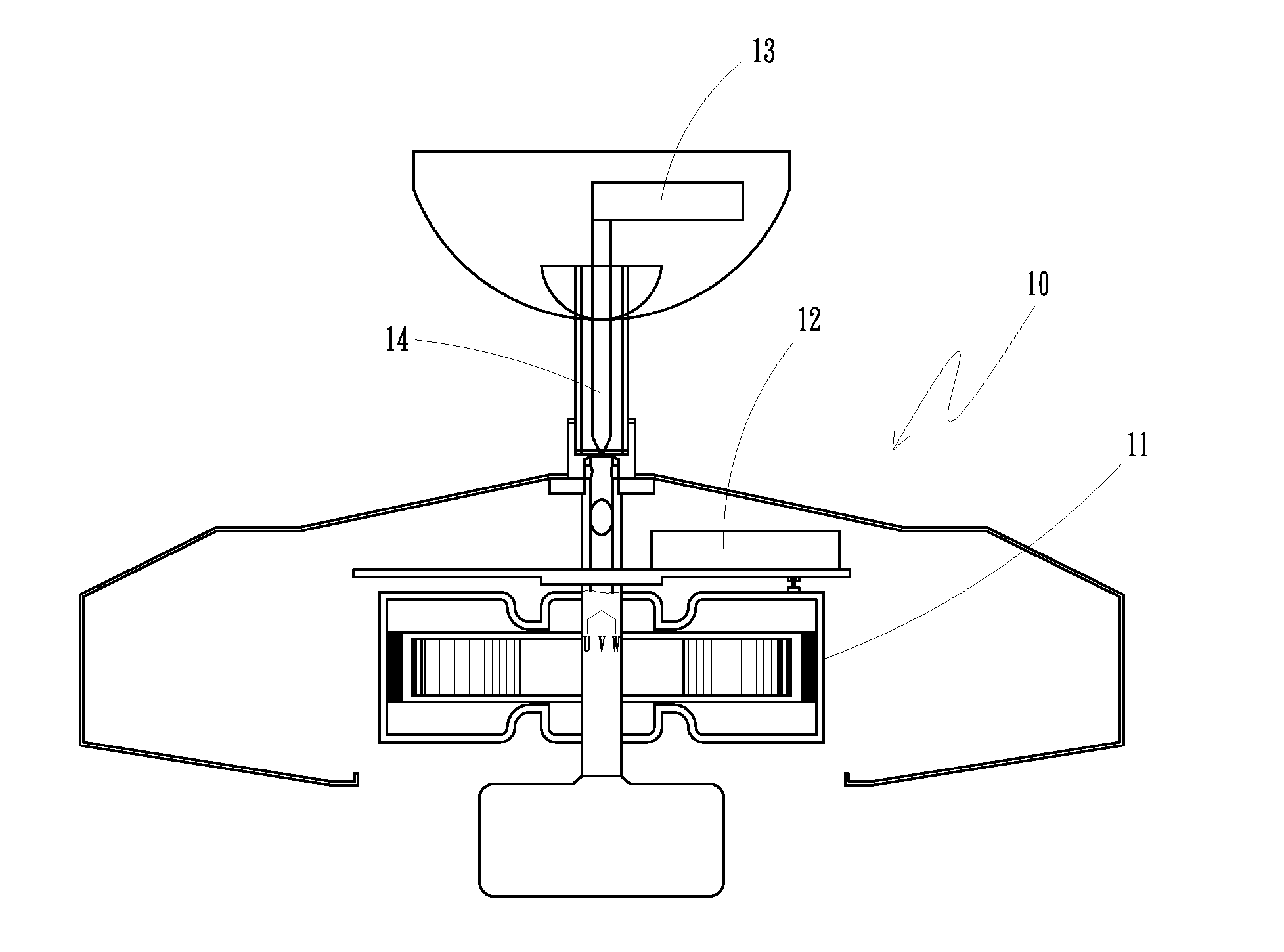
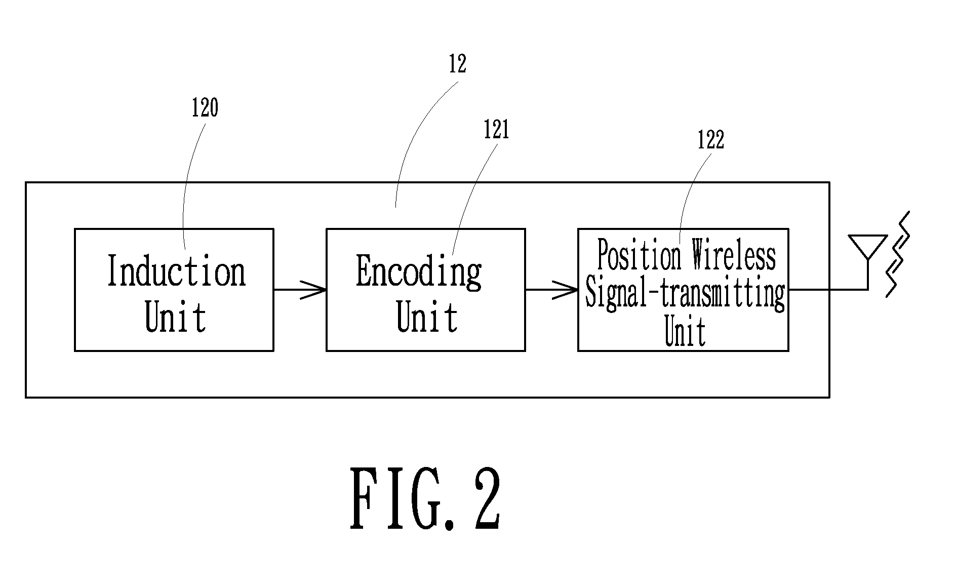
[0022]A ceiling fan 10 containing a motor 11 therein, a signal-transmitting device 12 located on top of the motor 11 and sharing the same axle with the motor 11, a signal receiving device 13 located above the ceiling fan 10, and an electric wire 14 connected between the signal receiving device 13 and the motor 11. In addition, an induction unit 120, an encoding unit 121 and a position wireless signal-transmitting unit 122 are all installed in the signal-transmitting device 12, and a position wi...


PUM


Abstract

A wireless signal transmission device for a DC brushless ceiling fan motor that includes a wireless signal transmission device to receive and transmit a signal to a controlling unit, and the controlling unit transmits the control signal to the motor via an electric wire. A wireless signal-transmitting device is installed above the motor. The signal-transmitting device detects the position of the motor and transmits a wireless signal to a signal receiving device, which then transmits the signal to the controlling unit, which further transmits the controlling signal to the motor via of the electric wire, for the purpose of controlling the rotation of the motor. Due to the fact that the signal is transmitted wirelessly, it is not necessary to use any destructive process such as drilling a hole on the body of the ceiling fan, and thus the rigidity and the strength of the components are preserved.

Description

BACKGROUND OF THE INVENTION[0001]1. Field of the Invention[0002]The present invention relates to a DC brushless ceiling fan motor. More particularly, the present invention relates to a wireless signal transmission device for detecting the position of the motor and controlling the speed of the motor.[0003]2. Description of Related Art[0004]A conventional DC brushless ceiling fan motor, as shown in FIG. 8, requires a sensor, such as the Hall sensor, to be installed within the motor to detect the variation of the magnetic field caused by the rotation of the magnet and to send a controlling signal to the motor for continuous and steady operation. The installation of a sensor ensures smooth operation as well as a successful start from a static state. The sensor 22 is installed above the motor 21 of the ceiling fan 20, a signal-transmitting wire 23 is connected with a controlling device 24 of the sensor 22. The position of the motor 21 can be detected by virtue of the sensor 22, which is ...

Claims


Application Information

Patent Timeline
Patent Type & Authority Patents(United States)
IPC IPC(8): G05D1/02
CPCF04D25/0606F04D25/088H02K11/0078H02K7/14H02K11/35
Inventor CHEN, CHIEN HSUN
Owner RHINE ELECTRONICS
Learn More