
Eye tracking system and method

a tracking system and eye tracking technology, applied in the field of eye tracking system and method, can solve the problems of eye strain, low market acceptance, discomfort,

Active Publication Date: 2010-01-26
SEEING MACHINES
View PDF12 Cites 36 Cited by
  • Summary
  • Abstract
  • Description
  • Claims
  • Application Information

AI Technical Summary

Benefits of technology

The present invention provides a system and method for predicting the future position of a person's head or face in a computerized environment. This is useful for applications such as eye tracking or face tracking. The system uses a camera to capture images of the person's head or face and a computer program to analyze those images and predict the future position of the person's head or face. This allows for real-time tracking of the person's movements. The system can be used in a head-mounted display or other applications that require information about the person's future position. The method involves processing the images of the person's head or face to estimate the likely future position and using this information to control the display or other applications. The system can also use multiple cameras to observe the person and improve the accuracy of the predictions.

Problems solved by technology

Such systems require the user to keep their head in this specified position during the whole experience and therefore have low market acceptance.
When looked at from a position other than the sweet spot, the image looses the impression of depth and becomes inconsistent, resulting in eye strain as the brain attempts to make sense of the images it perceives.
This eye strain can generate a feeling of discomfort very quickly which encumbers the market acceptance even more.
Although active auto-stereoscopic displays are much more practicable than passive displays, it has been found that such displays can suffer from the lag introduced by the head tracking system.
When moving the head, the time between the actual head motion and the adjustment of the display to the new head position causes an offset sufficiently large to break the impression of depth and the consistency of the images with the previously described problems.
In such applications visual consistency breakdowns during every head motion reduces the usability.

Method used


Image

  • Eye tracking system and method
  • Eye tracking system and method
  • Eye tracking system and method

Examples


Embodiment Construction

[0021]In the preferred embodiment, there is provided a method for reducing the adjustment lag of auto-stereoscopic displays to thereby improve their usability. Ideally, the method includes the utilisation of a prediction filter that is optimal for the requirements of auto-stereoscopic displays although other methods are possible.

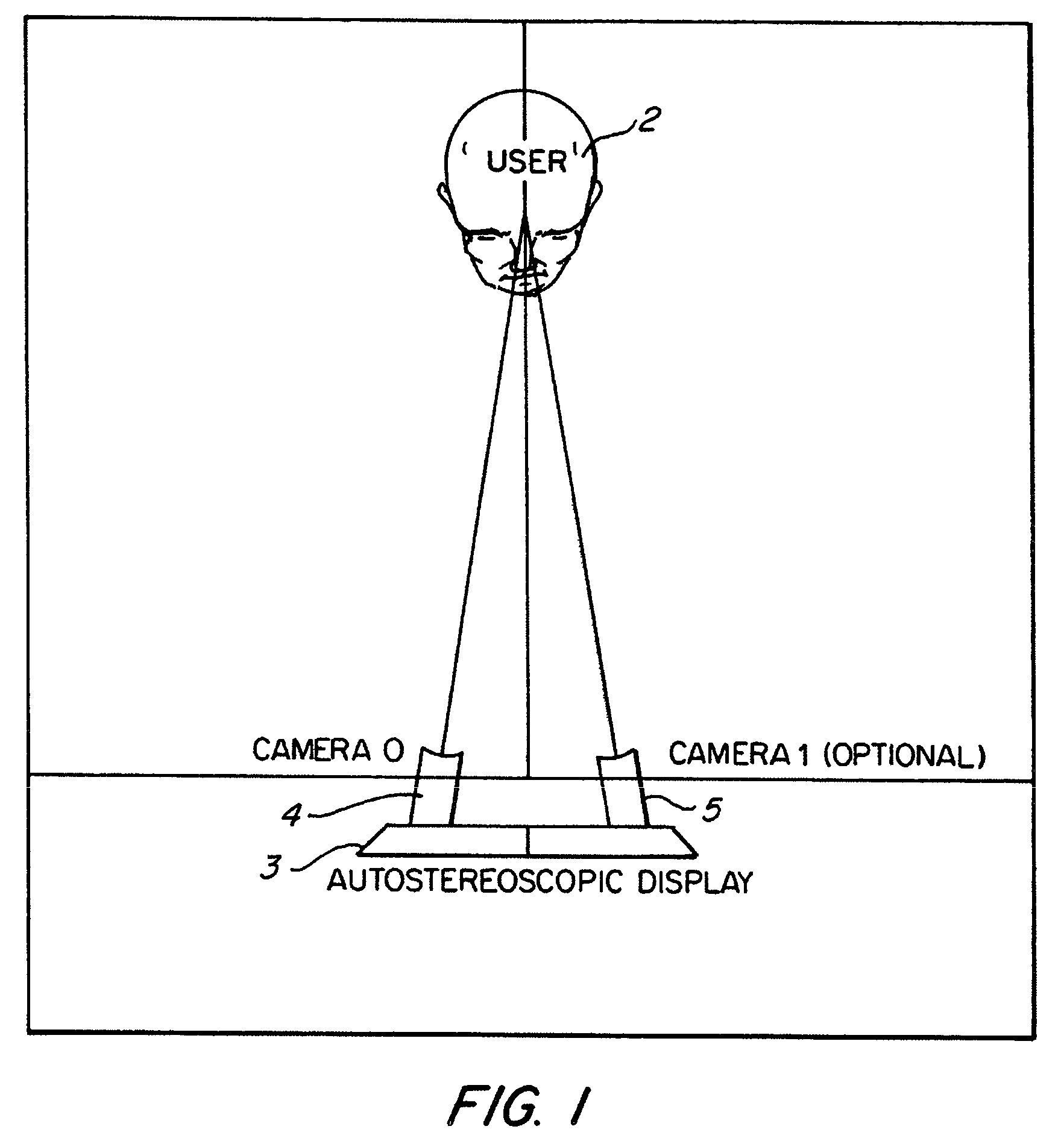
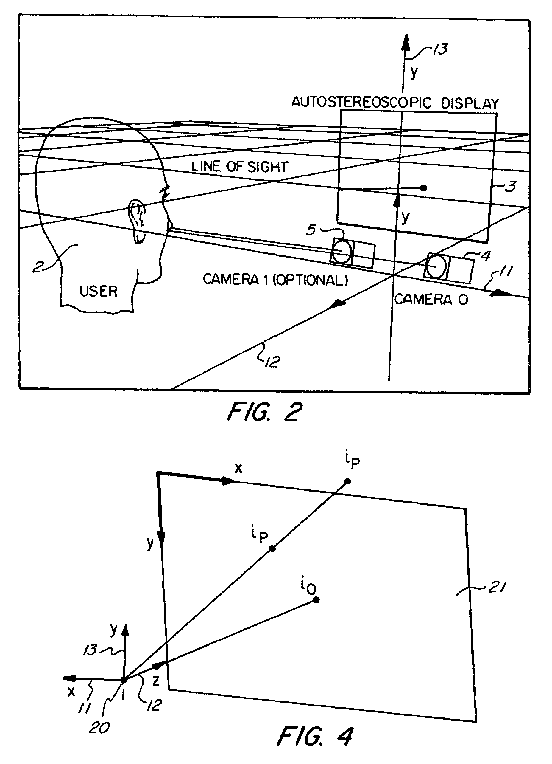
[0022]Turning initially to FIG. 1 and FIG. 2, there is illustrated schematically an arrangement of a system for use with the preferred embodiment wherein a user 2 is located in front of an automatic stereoscopic display 3. Two cameras 4, 5 monitor the user and their video feeds are processed to derive a current facial position. The cameras 4, 5 are interconnected to a computer system implementing facial tracking techniques.

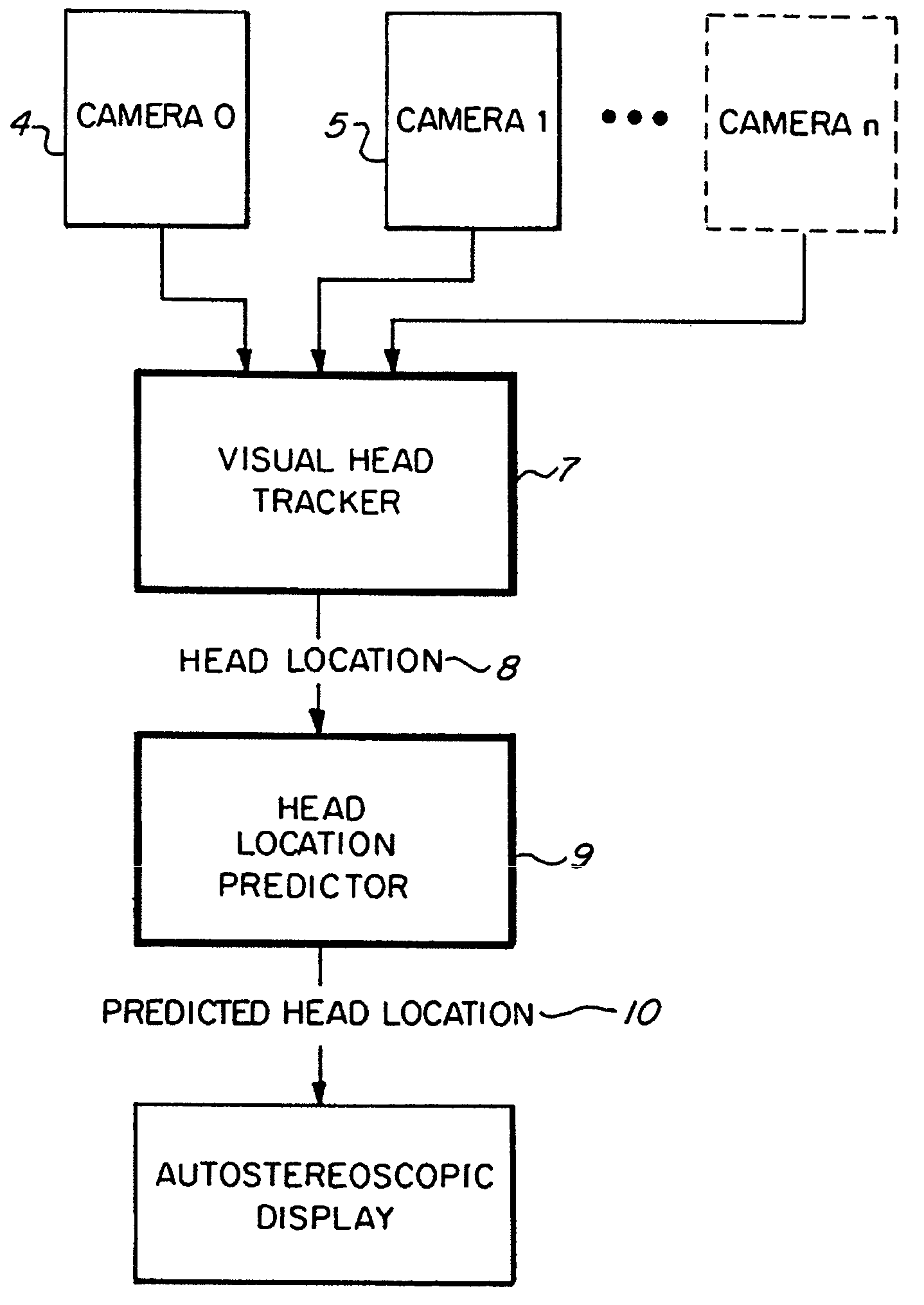
[0023]FIG. 3 illustrates schematically the subsequent operation of processing chain incorporating the preferred embodiment. The camera feeds e.g. 4,5, are fed to a visual head tracker 7 which tracks a current position of the user's head. T...


PUM


Abstract

A method of tracking an expected location of a head in a computerized headtracking environment having a delayed processing requirement for locating a current head position, the method comprising the step of: utilizing previously tracked positions to estimate a likely future tracked position; outputting the likely future tracked position as the expected location of the head. Kalman filtering of the previously tracked positions can be utilized in estimating the likely future tracked position.

Description

[0001]This application is a continuation of pending International Patent Application No. PCT / AU2004 / 000413 filed on Mar. 31, 2004 which designates the United States and claims priority of Australian Patent Application No. 2003901528 filed on Mar. 31, 2003.FIELD OF THE INVENTION[0002]The present invention relates to a system for accurate prediction of a current eye location and, in particular, discloses a system for head prediction suitable for utilisation in stereoscopic displays.BACKGROUND OF THE INVENTION[0003]Auto-stereoscopic displays give the observer the visual impression of depth, and are therefore specifically useful for applications in the CAD area, but also have applications in 3D gaming and motion picture entertainment. The impression of depth is achieved by providing the two eyes of the observer with different images which correspond to the view from the respective eye onto the virtual scene. For background information on Autostereoscopic Displays, reference is made to: ...

Claims


Application Information

Patent Timeline
Patent Type & Authority Patents(United States)
IPC IPC(8): G06K9/00G06F17/00H04N5/225G01S3/786G01S11/12G02B27/00H04N13/00H04N13/04
CPCG01S3/7865G01S11/12G02B27/0093H04N13/0402H04N13/0497H04N13/302H04N13/398
Inventor LONGHURST, GAVINROUGEAUX, SEBASTIAN
Owner SEEING MACHINES
Learn More