
Electricity removal apparatus

a technology of electric removal apparatus and ionization chamber, which is applied in the direction of electrical apparatus, electrostatic charge, relay, etc., can solve the problems of reducing the ability to produce ions, and achieve the effect of suppressing the occurrence of problems

Inactive Publication Date: 2010-01-19
KEYENCE
View PDF4 Cites 25 Cited by
  • Summary
  • Abstract
  • Description
  • Claims
  • Application Information

AI Technical Summary

Benefits of technology

This approach effectively suppresses wear and contamination of the electrode needle while maintaining efficient electricity removal from charged bodies, extending the apparatus's operational life and maintaining ion balance.

Problems solved by technology

Thus, the electricity removal apparatus has a problem, wherein the capability of producing the ion, decreases over time as the electrode needle becomes worn away and tainted.

Method used


Image

  • Electricity removal apparatus
  • Electricity removal apparatus
  • Electricity removal apparatus

Examples


Embodiment Construction

[0039]The following describes a preferred embodiment according to the present invention with reference to the appended drawings.

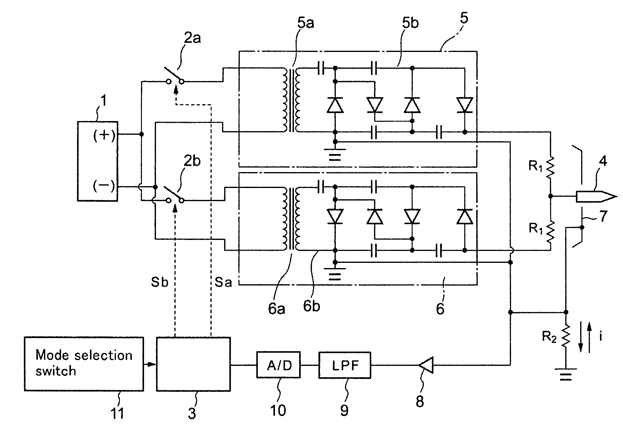
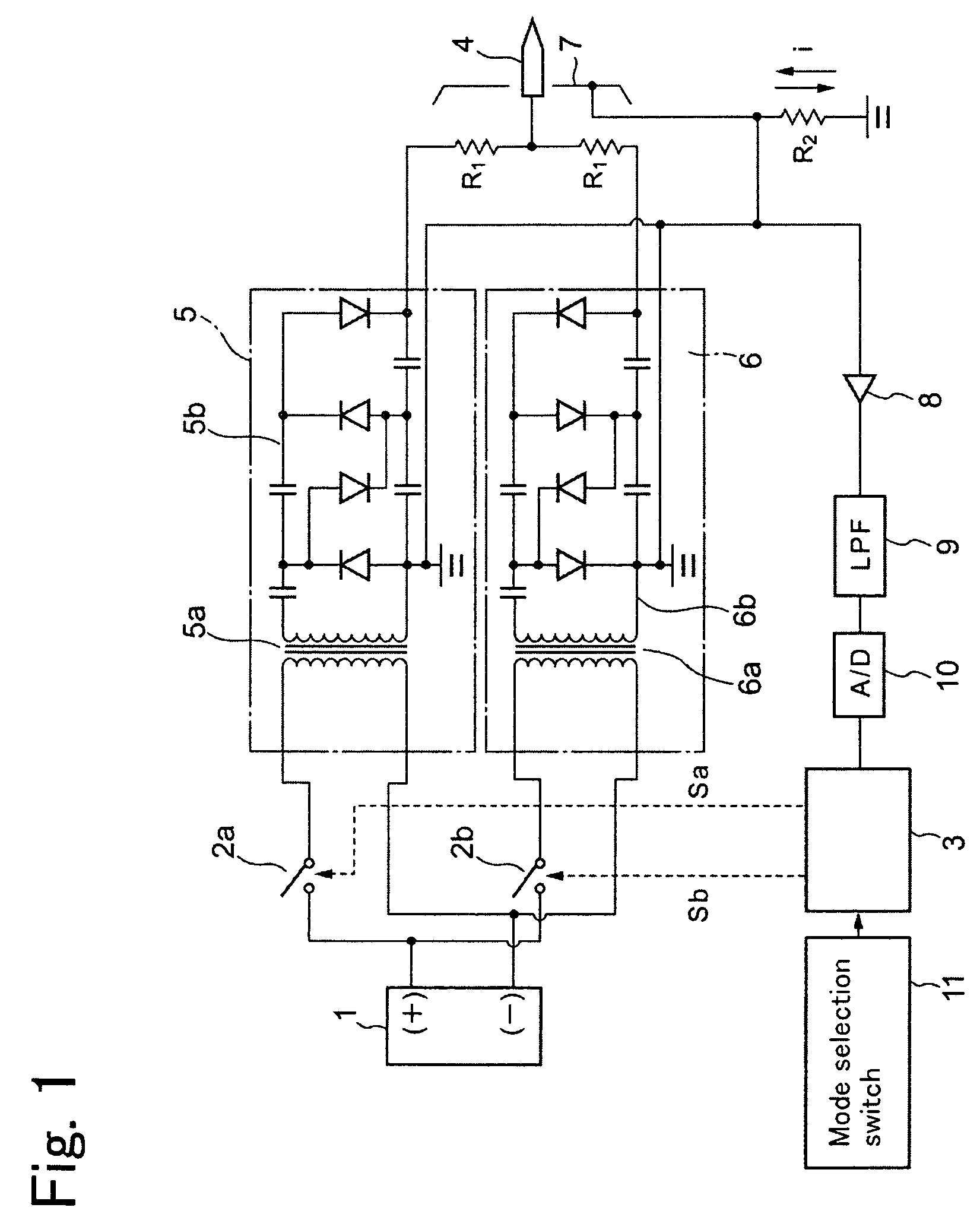
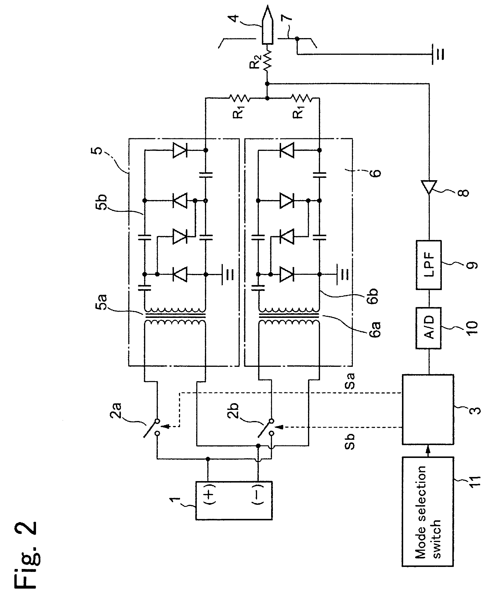
[0040]FIG. 1 is a circuit diagram of an electricity removal apparatus, namely an ionizer, according to one embodiment. In FIG. 1, numeral 1 represents a direct-current power supply, and constituted from an external direct-current power supply such as a secondary battery. Numeral 2a and numeral 2b respectively represent a first switch and a second switch provided on an output side of the direct-current power supply 1. The first switch 2a and the second switch 2b are controlled to open and close by control signals Sa and Sb from a control unit 3. Of course, electronic switches such as transistors can be used as the first switch 2a and the second switch 2b.

[0041]A positive terminal of the direct-current power supply 1 is connected via the first switch 2a with a first high voltage producing circuit 5 having a positive polarity including a transformer 5a and a ...


PUM


Abstract

The present invention relates to suppressing wear and contamination of the electrode needle as well as effectively removing the electricity from a charged body. An electricity removal mode in which the electrode needle is applied with a high voltage to produce ions and a halt mode in which the electrode needle is halted are provided, that are alternatively selected based on a selection of a user. The halt mode includes a halt period during which the high voltage is not basically applied on the electrode needle. When a self discharge occurs by approach of a charged body in this halt period and an absolute value of current that flows through the resistance exceeds the first threshold value, the electricity removal operation is initiated in which the high voltage is applied on the electrode needle to produce ions. Subsequently, after a predetermined time period passes, for example, the electricity removal operation is terminated and the halt period is resumed.

Description

CROSS-REFERENCE TO RELATED APPLICATION[0001]The present application claims priority from Japanese Patent Application Nos. 2006-343066, 2006-343067, and 2006-343068, all filed on Dec. 20, 2006, the entire contents of which are hereby incorporated by reference.BACKGROUND OF THE INVENTION[0002]1. Field of the Invention[0003]The present invention relates to an electricity removal apparatus for removing electricity of a charged body that is either positively or negatively charged.[0004]2. Description of Related Art[0005]An electricity removal apparatus, namely an ionizer, which removes the electricity of a charged body by producing positive or negative ions has been known (shown in Japanese Unexamined Patent Publication No. 2000-58290 and Japanese Unexamined Patent Publication No. 2003-86393). The electricity removal apparatus produces ions by a corona discharge onto an electrode needle by applying a high voltage. Thus, the electricity removal apparatus has a problem, wherein the capabil...

Claims


Application Information

Patent Timeline
Patent Type & Authority Patents(United States)
IPC IPC(8): H05F3/06
CPCH01T23/00
Inventor FUJITA, TSUKASAHASHIMOTO
Owner KEYENCE
Learn More