Tree grille system

a grille system and tree technology, applied in the direction of couplings, manufacturing tools, ways, etc., can solve the problem of not endangering the stability of the tree grille, and achieve the effect of convenient manufacturing

Inactive Publication Date: 2009-12-29
F VON LANGSDORFF LICENSING
View PDF18 Cites 2 Cited by
  • Summary
  • Abstract
  • Description
  • Claims
  • Application Information

AI Technical Summary

Benefits of technology

[0006]Due to the measure of configuring the ramp-type clamping surface of the fixed coupling parts on the peripheral side of a rib disposed on the underside of the segment pieces and of providing the fluting accordingly on this peripheral side of the rib, the longitudinal sides of the depressions and elevations of the fluting extend perpendicularly to the plane of the grille sections. Since a fluting disposed in such a manner is more easily accessible than a fluting in which the longitudinal sides of the depressions and elevations extend parallel to the plane of the grille sections, a possibly necessary reworking of the fluting is clearly simplified when producing the casting molds for the grille sections.
[0007]Due to the additional measure of inserting an insert into the receiving holes of the displaceable coupling part, said receiving holes being provided for a hook wrench, and the insert thereby filling out these holes, wherein a pin fixedly connected to the insert engages in one of several bores, which are disposed in a circular arc-shaped manner in the respective segment piece of both the fixed coupling parts, an absolutely secure form-fit locking of the displaceable coupling part is achieved even if the coupling part has not been rotated properly into the locking position using the prescribed target torque. In this manner the displaceable coupling parts are now secured in the best way possible against an automatic release from the locking position, with the result that dynamic loads of the tree grille also, as can arise e.g. in the case of vibrations and brake applications and starting procedures of motor vehicles, cannot endanger the stability of the tree grille.
[0008]Since in the case of the fixed coupling parts, the ramp-type clamping surface is configured in an inventive manner on the peripheral side of an arc-shaped rib, which is directed downwards from the underside of the segment piece, the fixed coupling parts are locked in place by tightening them against one another only in the horizontal direction, i.e. the direction extending parallel to the plane of the grille sections when locking the coupling. Due to this the sidewalls of the grille sections are pressed against one another in the longitudinal and cross directions. In this manner the grille sections are joined to form a tree grille, which is stiff, bend-proof and thus particularly highly loadable. This effect can be further intensified if the sidewalls according to claim 2 are configured such that they extend by a small measure obliquely inwardly. Due to this measure, two grille sections pressed on one another extend at a very flat angle towards one another. Consequently, the tree grille, which usually consists of a plurality of grille sections, is flatly arched upwardly in the unloaded state and thus is even more loadable than if it were extending in a planar form.
[0009]The refinement of the invention according to claim 3, as per which one bore for the pin of the insert is assigned to each depression and each rising flank of the fluting, makes it possible to lock the displaceable coupling part in finely stepped increments.
[0010]Due to the measure according to claim 4, as per which the inserts contain receiving openings for a handling tool, the inserts can be removed from the respective receiving hole of the displaceable coupling part only with the help of such a handling tool. Unless these handling tools are simple auxiliaries that are available to everyone, instead of being only special tools, it is possible in this manner to prevent unauthorized persons from pulling out the inserts from the receiving holes and thus nullifying the form-fit locking of the displaceable coupling parts.

Problems solved by technology

In this manner the displaceable coupling parts are now secured in the best way possible against an automatic release from the locking position, with the result that dynamic loads of the tree grille also, as can arise e.g. in the case of vibrations and brake applications and starting procedures of motor vehicles, cannot endanger the stability of the tree grille.

Method used


Image

  • Tree grille system
  • Tree grille system
  • Tree grille system

Examples


Embodiment Construction

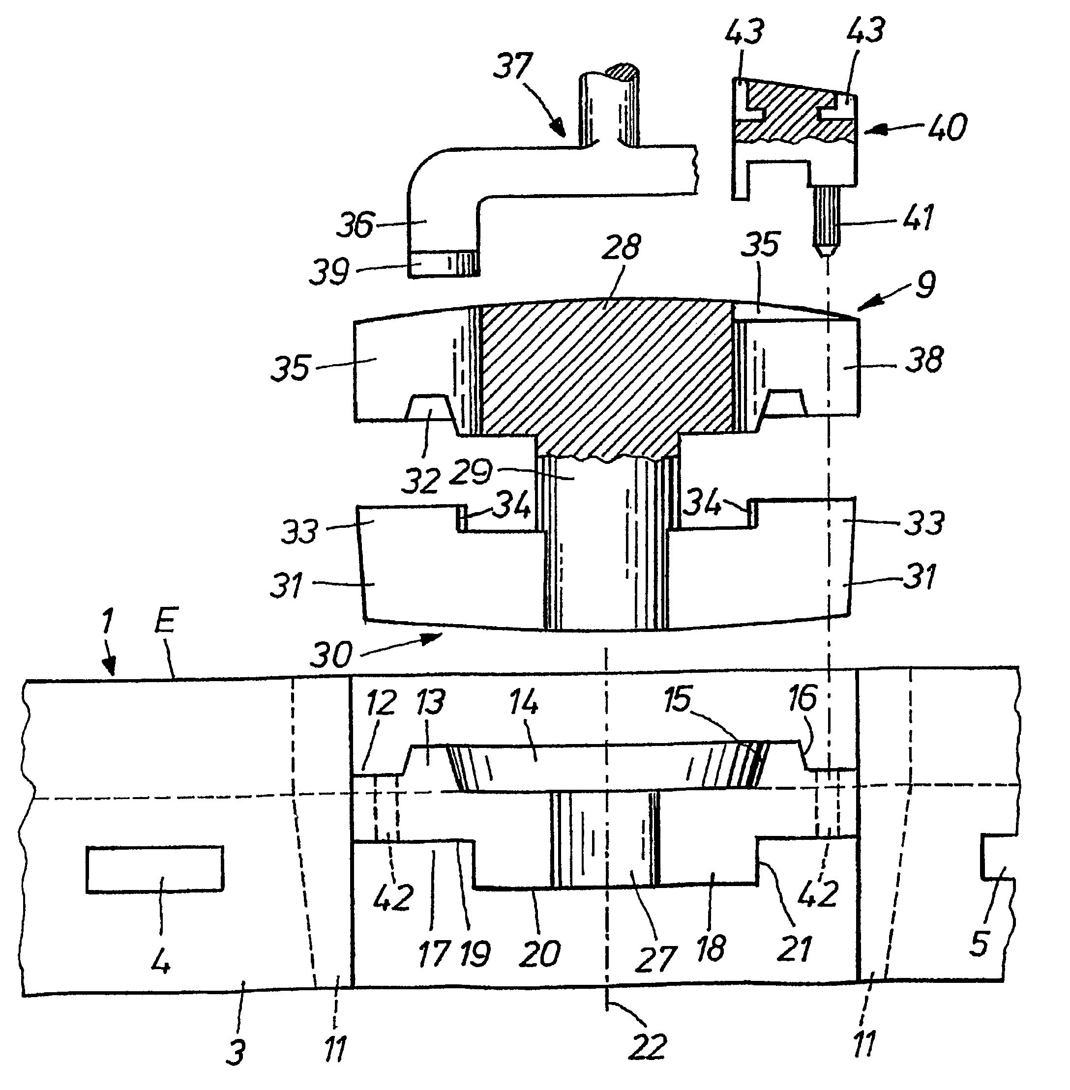
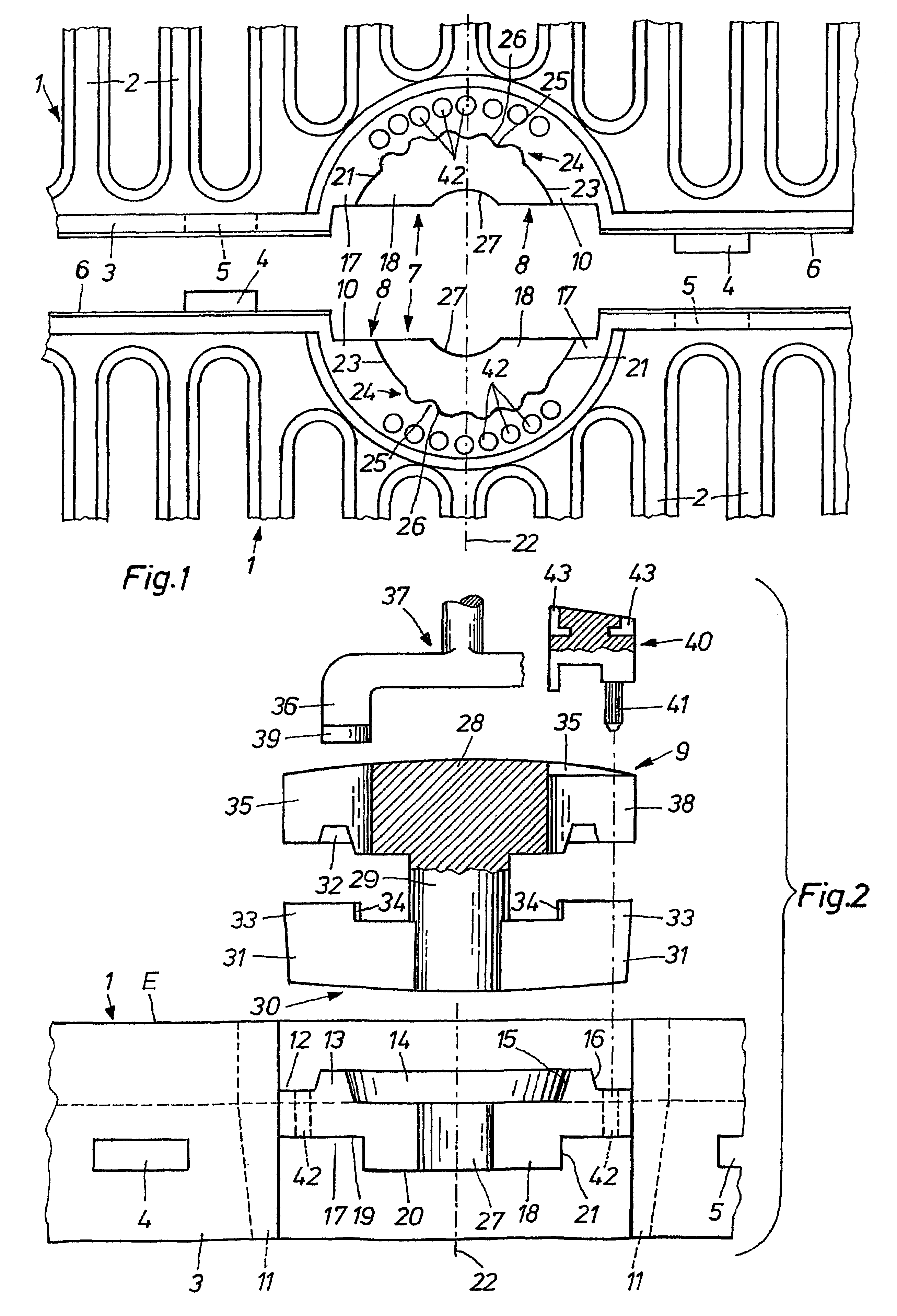
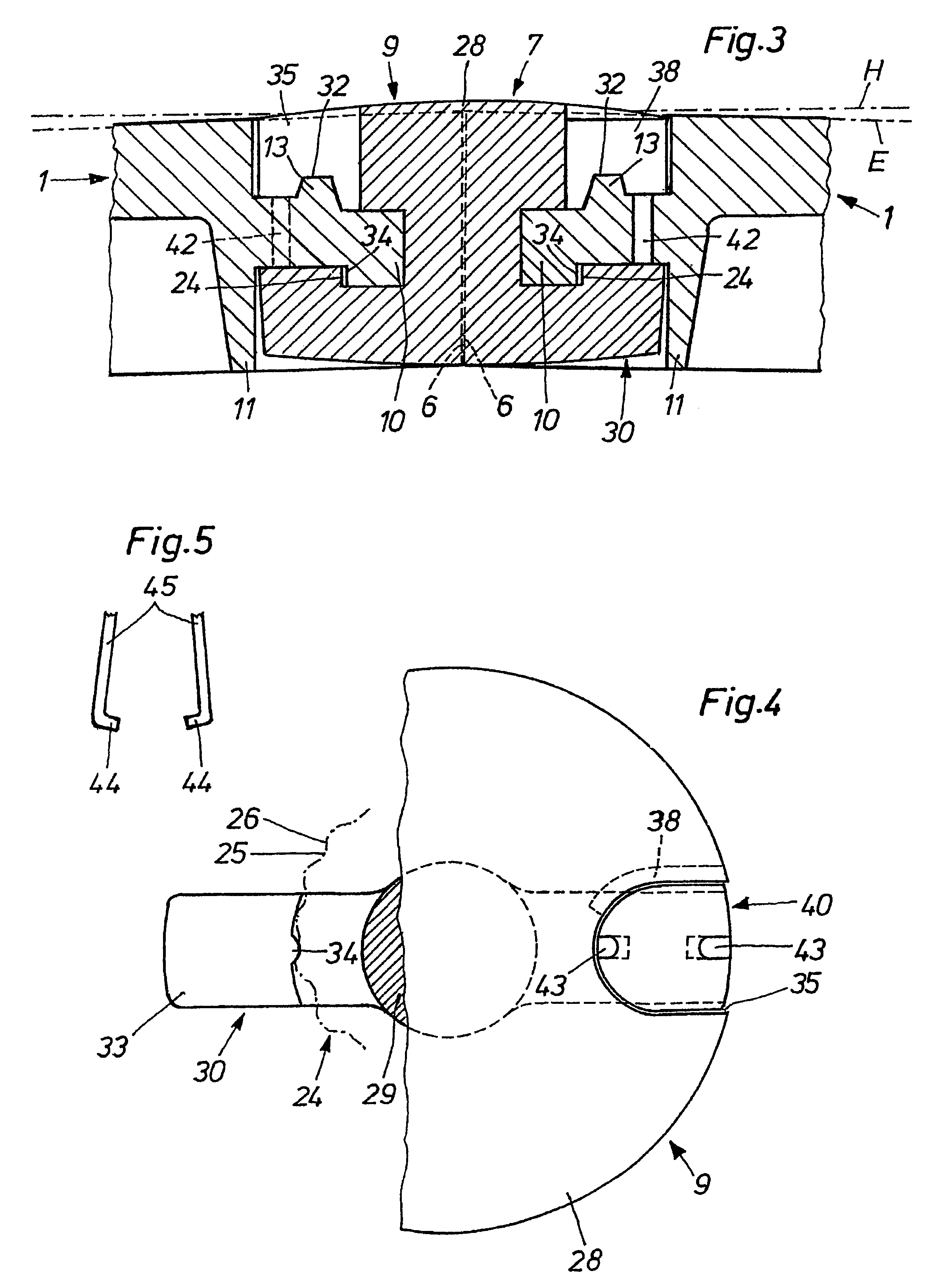
[0019]In a manner known per se, the tree grille system comprises a number of grille sections 1, said number being dependent on the size and shape of the area to be covered. The grille sections can be provided with a square, rectangular or circular segment shape for forming variably configured tree grilles.

[0020]The grille sections 1 comprise a plurality of downwardly tapering ribs 2 and are provided with circumferentially extending strips 3, which project downwardly beyond the underside of the ribs 2 and thus increase the flexural stiffness of the grille sections 1. As shown in FIG. 1, rectangular projections 4 and correspondingly shaped grooves 5 are configured alternately and at equal distances on the strips 3. When two grille sections 1 are placed together, the projections 4 slide into the grooves 5 and thus enable an accurate alignment of the grille sections 1 and a stiffening of the assembled tree grille. The outer sidewalls 6 of the strips 3 are tapered inwardly by a small mea...


PUM


Abstract

The invention relates to a tree grille system for covering tree grates. Said system consists of grille sections (1), which are interconnected by couplings (7) to form a self-supporting tree grille. The couplings (7) consist of two fixed coupling parts (8) configured on the grille sections (1) and a coupling part (9) that can be inserted between the other parts and then rotated into a locking position. An arc-shaped rib (18) is configured on the underside of the fixed coupling parts (8), the outer peripheral face (21) of said rib being configured as a ramp-type clamping surface (23). One section of said surface (23) is provided with undulating fluting (24). When the displaceable coupling part (9) is rotated into the locking position, teeth (34) that are formed on said part slide over the fluting (24), causing the displaceable coupling part (9) to be locked by a friction and positive fit in the locking position. Inserts (40), which can be introduced into two receiving holes (35) of the displaceable coupling part (9), comprise a pin (41) that projects outwards and engages in one of several arched bores (42) of the fixed coupling parts (8). This permits a more secure, positive-fit locking position to be achieved for the displaceable coupling part (9).

Description

[0001]This application is the National Stage of International Application No. PCT / EP2005 / 009407, filed on Sep. 1, 2004, which claims priority to Application No. 10 2004 044 712.8 filed in Germany on Sep. 16, 2004. The entire contents of these prior applications are incorporated herein by reference.I. FIELD OF INVENTION[0002]The invention relates to a tree grille system for covering tree grates.II. BACKGROUND OF THE INVENTION[0003]The German Patent Specification DE 199 40 911 C1 discloses a tree grille system, in which several grille sections are interconnected by means of couplings to form a continuous, self-supporting tree grille. The couplings consist of two fixed coupling parts configured on the grille sections and a coupling part, which can be inserted between the two fixed coupling parts and then rotated into a locking position. The fixed coupling parts are formed by segment pieces, which comprise a ramp-type clamping surface on the underside. The displaceable coupling part con...

Claims


Application Information

Patent Timeline
Patent Type & Authority Patents(United States)
IPC IPC(8): E01C11/22B25G3/00A01G13/02E01C9/00E01C9/10
CPCE01C9/005Y10T403/7005
Inventor WAGNER, GEORG
Owner F VON LANGSDORFF LICENSING
Why Eureka
Try Eureka