
Car navigation system

a technology for navigation systems and cars, applied in navigation instruments, instruments, transportation and packaging, etc., can solve the problems of large devices, annoying guidance voices, and difficulty in hearing sounds outside the vehicle, and achieve the effect of simple construction

Inactive Publication Date: 2009-12-22
DENSO CORP
View PDF16 Cites 1 Cited by
  • Summary
  • Abstract
  • Description
  • Claims
  • Application Information

AI Technical Summary

Benefits of technology

[0010]The present invention has been made in consideration of the foregoing. It is therefore an object of the present invention to provide a car navigation system that can notify a driver of approach to a specified guidance point during route guidance in an easily recognizable manner and can be provided in a relatively simple construction for this purpose.
[0011]In recent years, there is an increasing demand for providing a vehicle (automobile) with a remote control device called a haptic device. The single remote control device enables operations of various vehicle-mounted devices such as a car navigation system, car audio, air conditioner, electrically operated mirror, and direction indicator. The remote control device is equipped with an operation unit. Examples of the operation unit include a hemispheric operation unit called a trackball capable of rotary and pressing operations, a control knob inclinable in all directions, and a dial capable of rotary and pressing operations. For example, the remote control device is disposed at the left of the driver's seat (near the shift lever in a right-hand-drive car) or a similar place where the driver can easily operate the remote control device at hand without extending his or her arm. To complete the invention, the inventors gave attention to such remote control device and confirmed that the use of the remote control device can solve the above-mentioned problem.
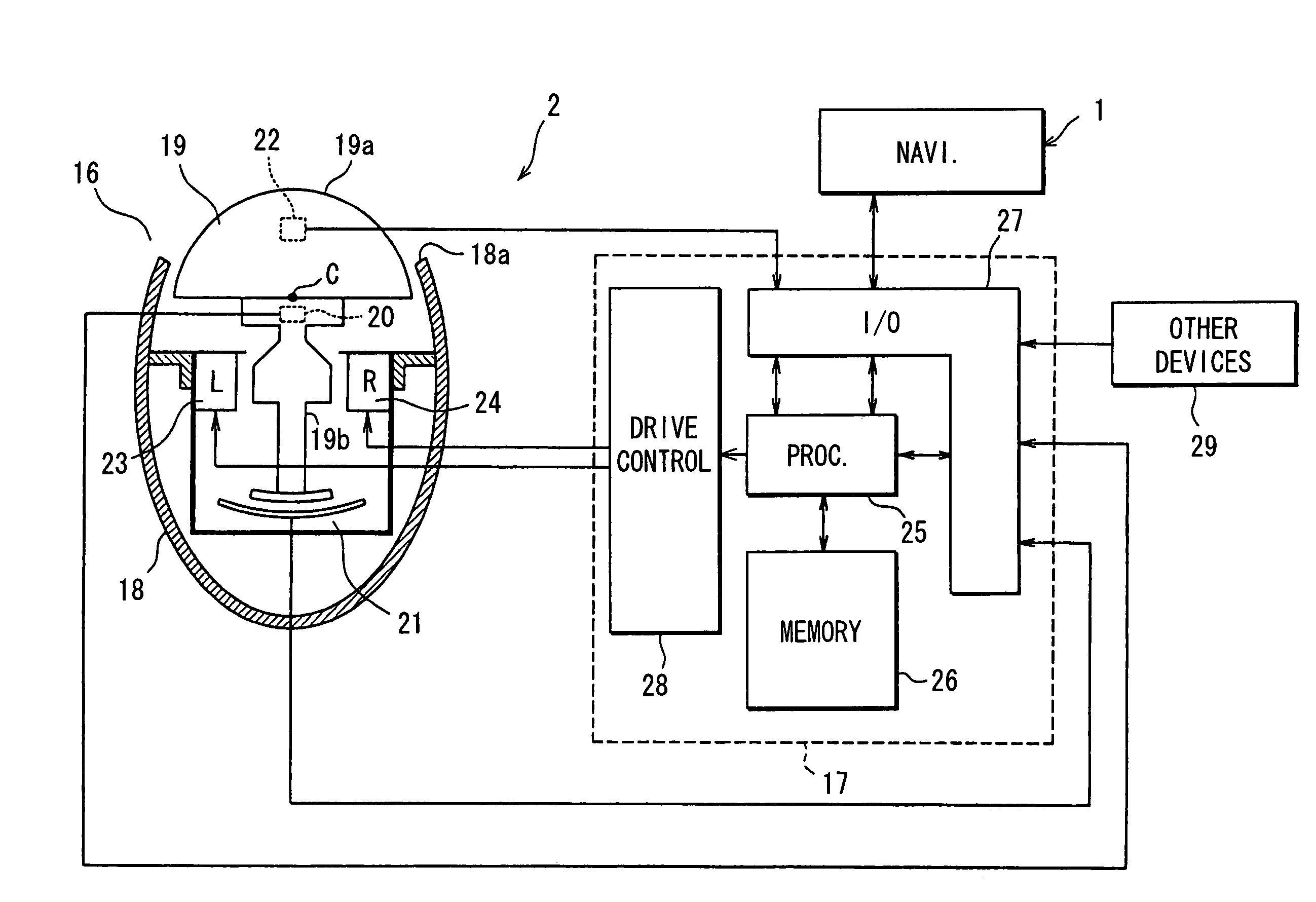
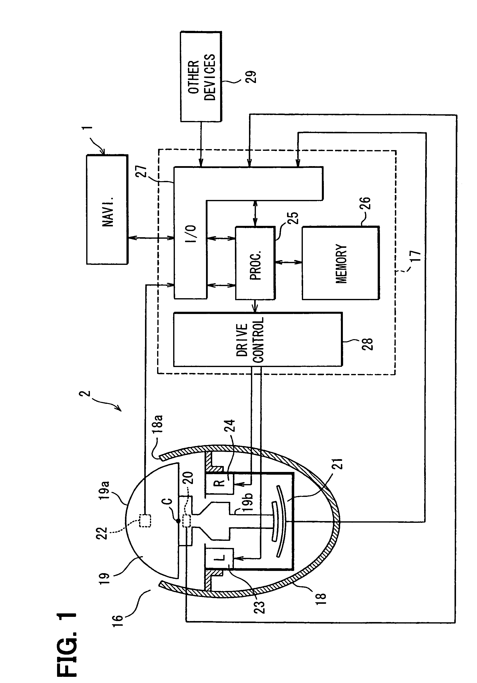
[0013]According to the invention, the vibration guiding unit vibrates the remote control device when the vehicle position approaches a guidance point during execution of the route guidance function. The driver feels the vibration while touching the remote control device by hand and can tactually recognize that the vehicle approaches the guidance point. In this case, the notification is made not through the sense of sight or hearing, but through such a manner more easily recognizable to the driver as to directly apply vibration to the body. The driver can be easily notified that the vehicle approaches the specified guidance point. Since the remote control device is provided originally for operations of the vehicle-mounted devices, the remote control device can be relatively simply constructed without the need to add a large-scale device.

Problems solved by technology

Reversely, the guidance voice may make it difficult to hear sounds outside the vehicle.
A fellow passenger may feel the guidance voice annoying while he or she is sleeping or listening to the music.
The device becomes large-scale, requires complicated installation works, and greatly increases costs.
Vibrating the seat or steering wheel makes it difficult for the driver to determine whether the guidance instructs the driver to turn to the left or right.
Further, some drivers may be surprised or displeased at sudden vibration.

Method used


Image

  • Car navigation system
  • Car navigation system
  • Car navigation system

Examples


Embodiment Construction

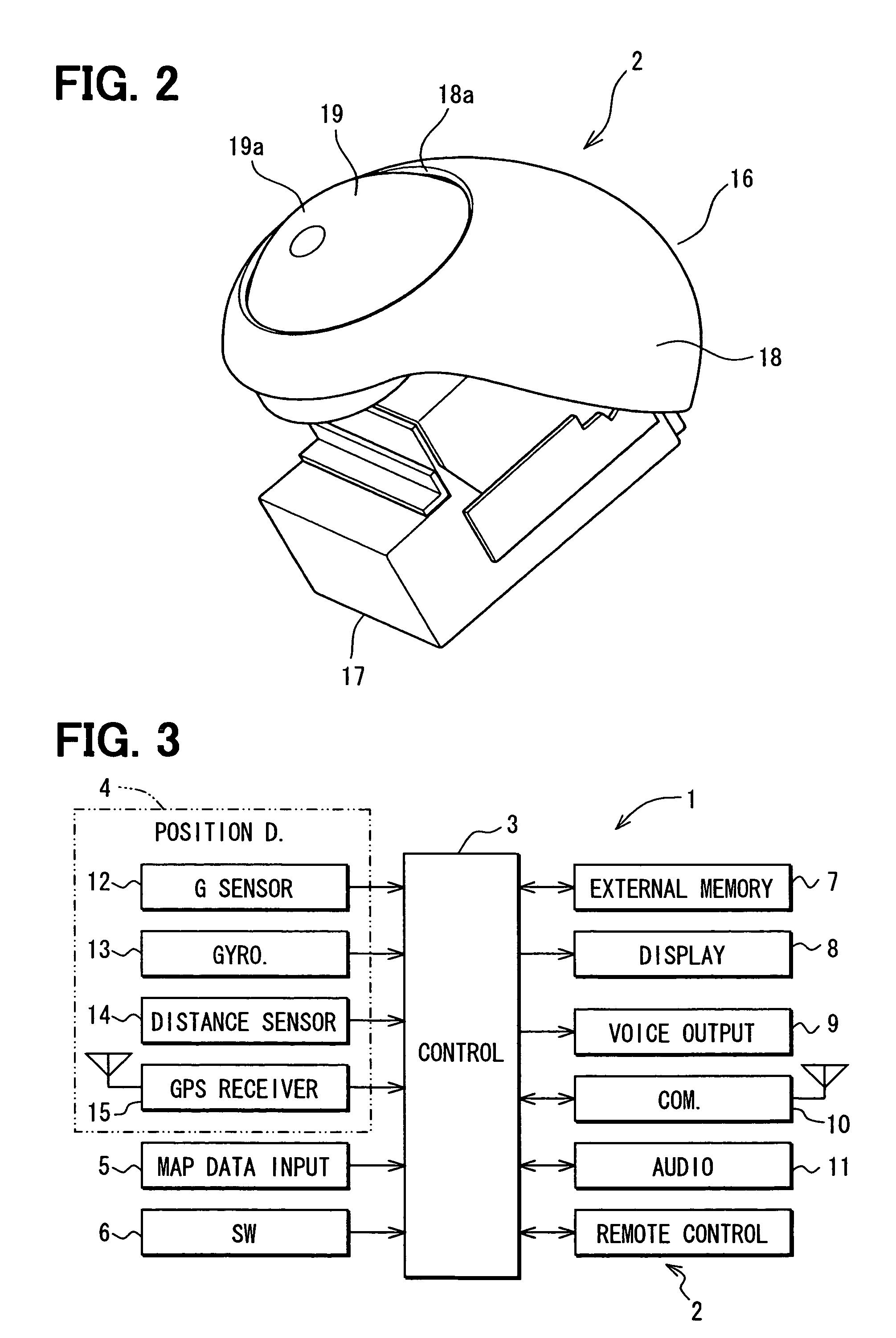
[0020]A car navigation system as an example of an embodiment of the invention will be described with reference to FIGS. 1 through 4. The car navigation system is built into a vehicle (automobile). The car navigation system includes a car navigation device 1 (see FIGS. 1 and 3) and a remote control device 2 (see FIGS. 1 through 3) called a haptic device. Referring now to FIG. 3, the car navigation device 1 will be described concisely.

[0021]FIG. 3 schematically shows an electric construction of the car navigation device 1. The car navigation device 1 has a control circuit 3 mainly including a microcomputer composed of a known CPU, ROM, RAM, I / O, and the like. The control circuit 3 connects with a position detector 4, a map data input device 5, an operation switch group 6, an external memory 7, a display device 8, a voice output device 9, and a communication device 10. The position detector 4 detects a position (or current position) of the vehicle. The display device 8 represents a col...


PUM


Abstract

A remote control device in a vehicle is provided in proximity of a driver's seat such that an operation unit of the remote control device is manually rotated and pressed by a hand of a driver in a driver's seat. A case of the remote control device contains vibrators to vibrate left and right sides of the remote control device. A navigation device is connected to a control unit of the remote control device. When a position of the vehicle approaches a specified guidance point during route guidance, the navigation device outputs a guidance signal (left-turn or right-turn instruction) to the control unit. When supplied with the guidance signal, the control unit controls driving of the vibrators to vibrate the remote control device based on the guidance signal.

Description

CROSS REFERENCE TO RELATED APPLICATION[0001]This application is based on and incorporates herein by reference Japanese Patent Application No. 2005-353597 filed on Dec. 7, 2005.FIELD OF THE INVENTION[0002]The present invention relates to a car navigation system that is mounted in a vehicle and has a location function to detect vehicle positions and a route guidance function to indicate a route to a destination.BACKGROUND OF THE INVENTION[0003]Generally, a vehicle-mounted car navigation system has a route guidance function. During the route guidance, let us suppose that a vehicle position approaches a specified guidance point such as an intersection for right or left turn or an entry to or an exit from an express highway. In such case, a screen display on a display device changes to an enlarged map near the intersection. In addition, the system provides voice guidance such as “turn to the left 300 m ahead” or “turn to the left ahead.”[0004]Such voice guidance is effective because it e...

Claims


Application Information

Patent Timeline
Patent Type & Authority Patents(United States)
IPC IPC(8): G01C21/30G01C21/32B60Q1/26G08B5/22
CPCG01C21/3652
Inventor YAMADA, YASUFUMI
Owner DENSO CORP
Learn More