
Optical imaging device

a technology of optical imaging and scanning device, which is applied in the direction of instruments, television systems, planar/plate-like light guides, etc., can solve the problems of limiting the overall speed of current flatbed scanning devices, slow scanning speed, and slow scanning speed of current flatbed scanners

Inactive Publication Date: 2009-12-15
RULING OPTICS
View PDF46 Cites 6 Cited by
  • Summary
  • Abstract
  • Description
  • Claims
  • Application Information

AI Technical Summary

Benefits of technology

"The present invention is an optical imaging device that includes a housing with a transparent platform for supporting a stationary image. The device also includes an illuminating plate and a number of image heads. The illuminating plate has a light guiding layer, a diffuser layer, and an open cell. The image heads are positioned to capture the image on the platform and transmit it to an image processing system. The device can be used for various applications such as surveillance or security. The technical effects of the invention include improved image quality, reduced image blur, and improved image processing."

Problems solved by technology

However, scanners currently available on the market have not benefited greatly from the technical advances and price reductions.
In particular, one of many drawbacks associated with current scanning devices such as flatbed scanner is that scanning speed is very slow, as slow as 30 second per page.
Among the many factors limiting the scanning speed such as line scan rate of optical sensor, data transferring rate, imaging processing speed, the speed of the mechanical movement of the scan heads is believed to be a major factor that limits the overall speed of current flatbed scanning devices.
Because light has to pass through the large area sensor, the sensor has low image capturing resolution.
The viewing angle of the field of view of the “camera” inside the box is limited.
Therefore, it is difficult to capture the image of a large document without making the vertical dimension of the device relatively high.
The bulky body of such a device makes it hard to be accepted as a document image-capturing device used in common offices.
The sub-images taken by the disclosed imaging system are initially distorted and have un-even shading.
Therefore, a heretofore unaddressed need exists in the art to address the aforementioned deficiencies and inadequacies.

Method used


Image

  • Optical imaging device
  • Optical imaging device
  • Optical imaging device

Examples


Embodiment Construction

[0063]The present invention is more particularly described in the following examples that are intended as illustrative only since numerous modifications and variations therein will be apparent to those skilled in the art. Various embodiments of the invention are now described in detail. Referring to the drawings, like numbers indicate like components throughout the views. As used in the description herein and throughout the claims that follow, the meaning of “a”, “an”, and “the” includes plural reference unless the context clearly dictates otherwise. Also, as used in the description herein and throughout the claims that follow, the meaning of “in” includes “in” and “on” unless the context clearly dictates otherwise.

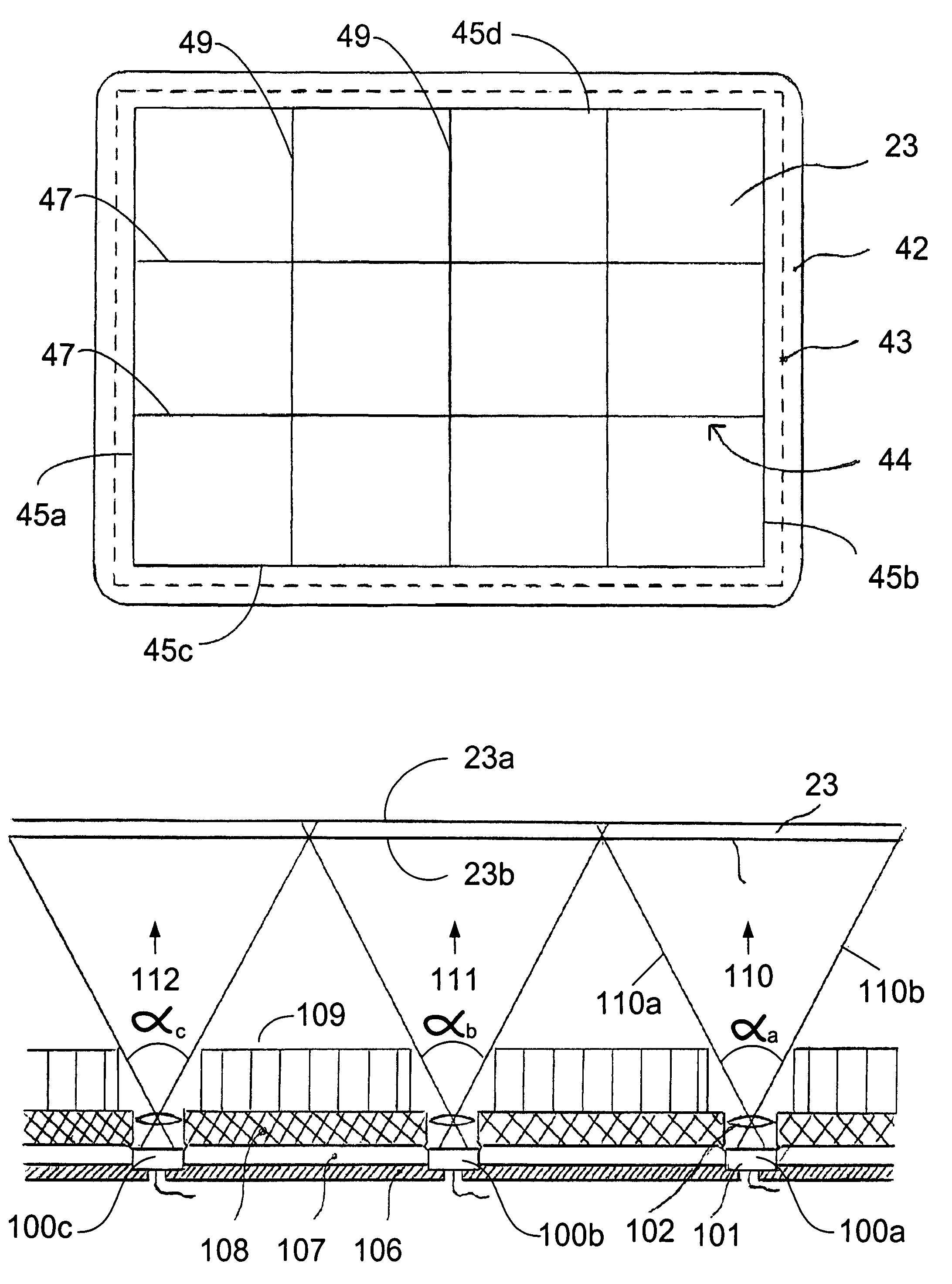
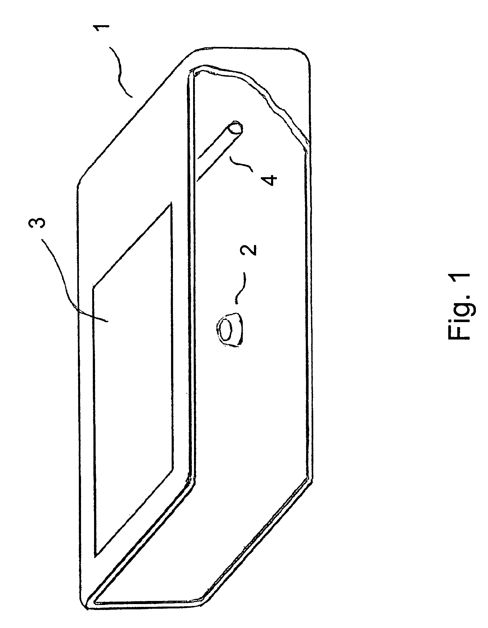
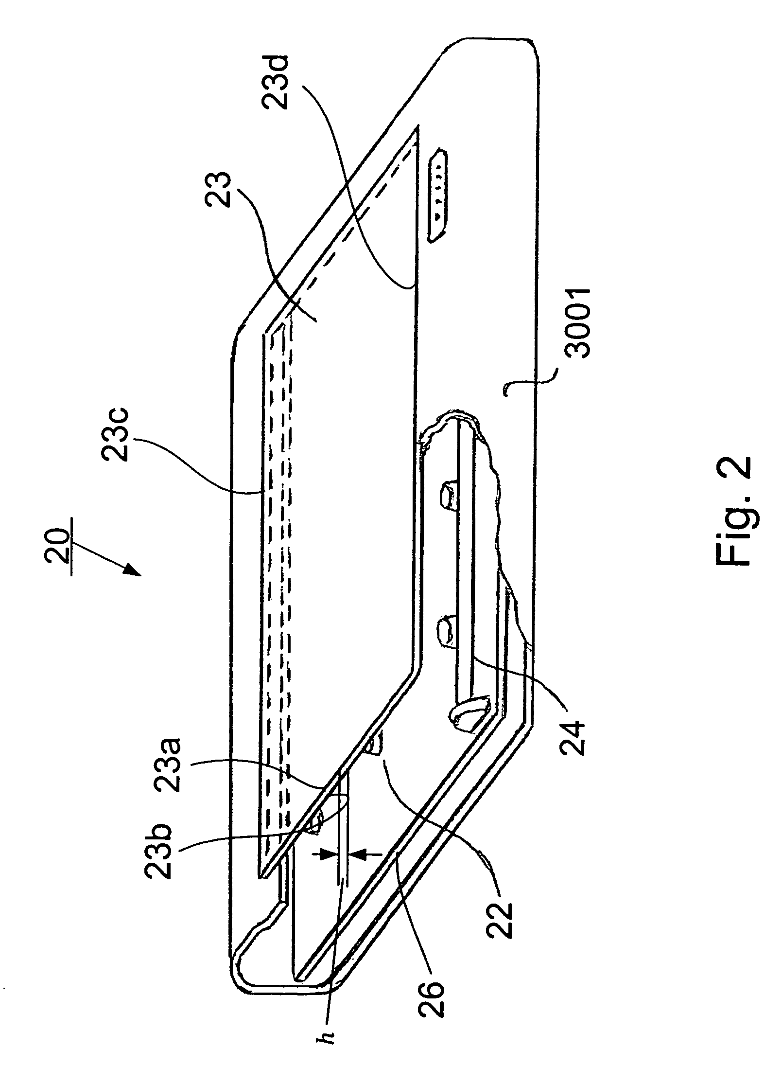
[0064]The description will be made as to the embodiments of the present invention in conjunction with the accompanying drawings 2-30. In accordance with the purposes of this invention, as embodied and broadly described herein, this invention, in one aspect, relates to an ...


PUM


Abstract

An optical imaging device for obtaining an image of a stationary image placed on an at least partially transparent platform. In one embodiment, the optical imaging device includes at least one illuminating plate having at least one open cell, at least one imaging head received in the at least one open cell of the at least one illuminating plate, and a light source adapted for emitting a light, where the at least partially transparent platform, the at least one illuminating plate, and the light source are arranged such that when in operation, a light emitted from the light source is directed into the at least one illuminating plate so that the light is evenly spread toward the at least partially transparent platform, reflected off the stationary image placed on the at least partially transparent platform and received by the at least one image head to obtain the image of the stationary image placed on the at least partially transparent platform.

Description

CROSS-REFERENCE TO RELATED PATENT APPLICATION[0001]This application is a continuation-in-part of U.S. patent application Ser. No. 10 / 960,791, filed Oct. 7, 2004, now U.S. Pat. No. 7,164,518 entitled “FAST SCANNER WITH ROTATABLE MIRROR AND IMAGE PROCESSING SYSTEM,” by Yuping Yang, the disclosure of which is hereby incorporated herein by reference in its entirety, which itself claims the benefit, pursuant to 35 U.S.C. §119(e), of provisional U.S. patent application Ser. Nos. 60 / 510,185, 60 / 531,249, and 60 / 572,639, filed on Oct. 10, 2003, Dec. 19, 2003 and May 19, 2004, respectively, entitled “FAST SCANNER WITH ROTARY MIRROR AND IMAGE PROCESSING SYSTEM,” by Yuping Yang, which are incorporated herein by reference in their entireties.[0002]Some references, which may include patents, patent applications and various publications, are cited in a reference list and discussed in the description of this invention. The citation and / or discussion of such references is provided merely to clarify ...

Claims


Application Information

Patent Timeline
Patent Type & Authority Patents(United States)
IPC IPC(8): H04N1/387H04N1/04G02B26/08H04N5/225
CPCG02B6/0016G02B6/005G02B6/0051H04N1/10H04N1/19584H04N1/19589G02B6/4298H04N2201/0081H04N1/195G02B2006/0098
Inventor YANG, YUPING
Owner RULING OPTICS
Learn More