
System for confirming hit locations on tennis court boundaries

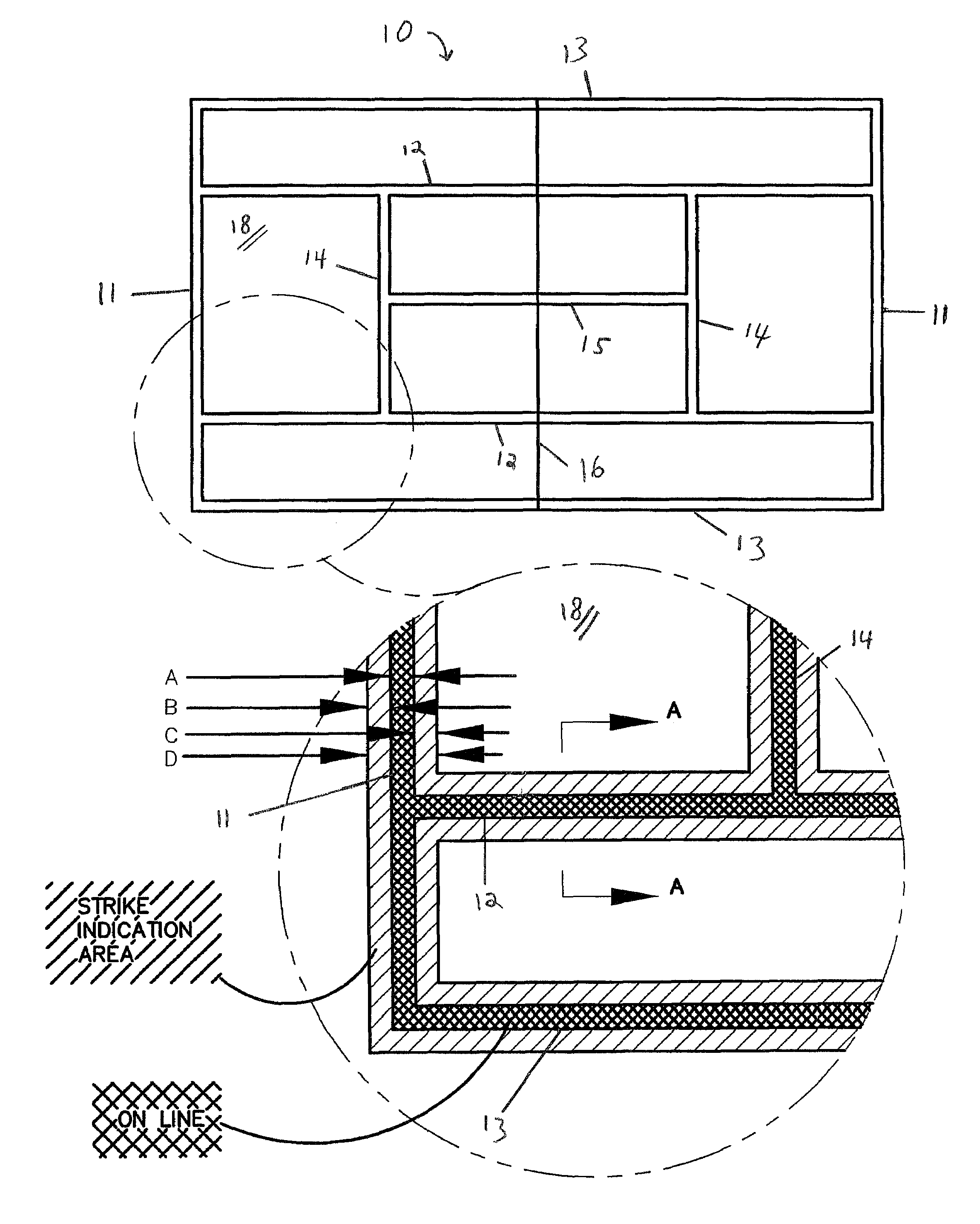
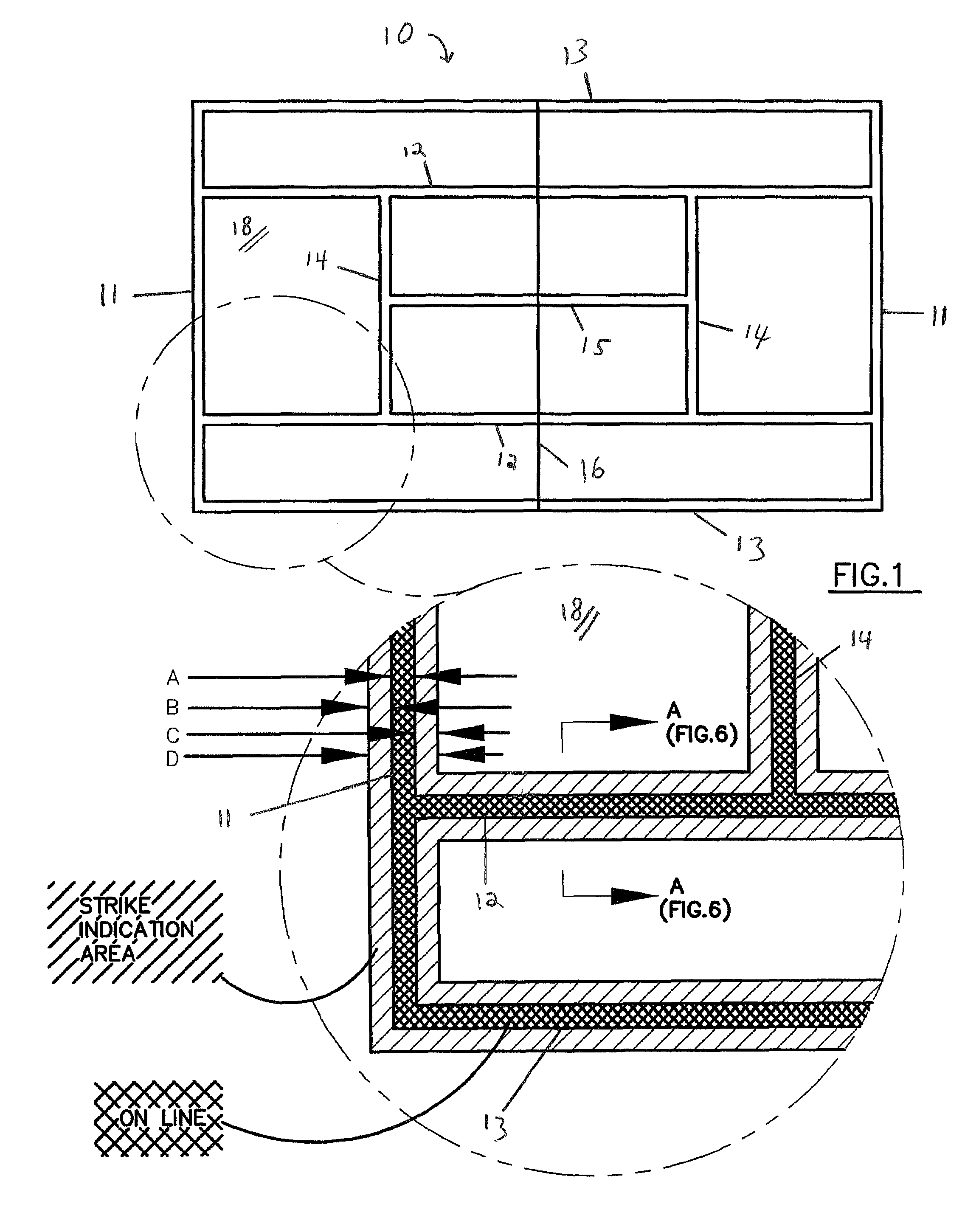
a technology for tennis courts and hit locations, applied in the field of tennis court hit locations confirmation systems, can solve problems such as errors and could occur, not being developed for use in international tournaments, and complicated and expensive installation and operation systems

Inactive Publication Date: 2009-12-15
WRITE STUFF ENTERPRISES
View PDF7 Cites 28 Cited by
  • Summary
  • Abstract
  • Description
  • Claims
  • Application Information

AI Technical Summary

Benefits of technology

Provides a simple, cost-effective, and accurate method for determining ball in-bounds or out-of-bounds calls, with quick color changes visible to officials and spectators, and reversible markings that do not interfere with subsequent plays.

Problems solved by technology

Although line judges and / or umpires use their best ability to make accurate calls, sometimes errors happen and could happen.
This system has only been used as theatre for the T.V. audience, and has not been developed for use in international tournaments.
This is an elaborate and expensive system for installation and operation.
However, the majority of tennis courts cannot use many of these sophisticated and expensive systems.

Method used


Image

  • System for confirming hit locations on tennis court boundaries
  • System for confirming hit locations on tennis court boundaries
  • System for confirming hit locations on tennis court boundaries

Examples


example 1

[0068]Schenectady® resin HRJ 40234 (SI Group, Schenectady, N.Y.) 8 ml was combined with Schenectady® 14894 microcapsules 32 ml, and a commercial acrylic latex, Minwax® 1265K 16 ml (approximately 30% solids by weight). This material was brushed onto a dark green tennis court coating, World Class Athletics® #TCP065 (World Class Athletic Surfaces, Leland, Miss.) on a hardboard, target Tennis balls were hit to impact the target and markings were inspected and photographed. Bluish-purplish marks were evident, with oval shapes, indicating that the single-paper system of carbonless carbon paper could provide a marking. However scuffs from tennis shoes also marked the coating the same color, indicating that these commercial materials would not be satisfactory for use as a ball impact marking system. We perceive that a stronger shell might be able to respond differently to ball impacts and shoe impacts and may be workable in a single coating system.

example 2

[0069]An alkaline latex court coating was made with cornstarch, 5 gm stirred into water, 20 ml. This was added to sodium hydroxide, 2 gm, dissolved in water, 20 ml. The resultant mixture was added to MinWax clear acrylic latex, 15 ml giving a smooth white mixture, easy to brush, but difficult to spray.

[0070]Tennis balls were treated with alum mordant and then were contacted with a solution of phenol red dye, 0.5 gm dissolved in denatured alcohol, 10 ml, plus ethoxyethane, 10 ml. The balls turned an orange color, and they were rinsed five times with denatured alcohol to remove superficial dye.

[0071]Tennis ball impacts of these balls on a target with the C-2 coating gave discernible, but not distinct marks.

example 3

[0072]A court coating was made 0.5 grams of Crystal Violet Lactone dye dispersed in Kwal® (Kwal Paint, Denver, Colo.) brand of satin acrylic latex, 15 ml. A tennis ball was treated with a solution of salicylic acid, 32 grams in denatured alcohol, 400 ml (overnight contact, water rinse, dried). The ball was pressed onto the CCP-6 coating and rotated a quarter turn. It made no mark on the coating. A drop of this salicylic acid solution on the coating caused color change to blue, but it was difficult to discern the color difference between the blue and the green background.


PUM


Abstract

The present invention is an article and process for determining the site of impact of a movable object on a treated surface, where a tennis ball is treated with a striking composition, and a boundary line region is treated with a receiving composition such that when the striking composition and the receiving composition are in physical contact, a calorimetric indicator is left on the receiving composition to indicate the point of contact.

Description

INDEX TO RELATED APPLICATIONS[0001]This application claims the benefit of U.S. Provisional Patent Application Ser. No. 60 / 745,284, filed Apr. 21, 2006. The disclosure of which is incorporated herein by reference in its entirety.BACKGROUND OF THE INVENTION[0002]Tennis courts and other sports use well-marked boundaries to define whether a ball is in play or out of play. If any part of a ball contacts the white line, it is in play; if it is outside of the white line it is out of play. In tennis, the boundaries are definitive for both serves and for rallies in accordance with rules of the International Tennis Federation.[0003]In competitive tennis, calls are usually made by line judges who view from an extrapolation of the line being judged, and calls may be over-ruled by an umpire sitting on a chair along the net line at the center of the tennis court. Balls may be traveling at more than 100 miles per hour, and very fast observation and perception is required for accurate calls.[0004]T...

Claims


Application Information

Patent Timeline
Patent Type & Authority Patents(United States)
IPC IPC(8): A63B71/00A63B71/06
CPCA63C19/065A63B71/0608A63B45/02A63B2243/0083A63B2102/02
Inventor RODENGEN, JEFFREYTYZZER, ROGERHAUSER, RAY L.
Owner WRITE STUFF ENTERPRISES
Learn More