
Rear structure of a vehicular body

a rear structure and vehicular body technology, applied in the direction of superstructure connections, roofs, transportation and packaging, etc., can solve the problems of inevitably increasing manufacturing costs and the weight of the vehicular body, and achieve the effect of preventing an upward bending of the side rear member and minimizing the number and weight of components

Active Publication Date: 2009-12-15
NISSAN MOTOR CO LTD
View PDF30 Cites 27 Cited by
  • Summary
  • Abstract
  • Description
  • Claims
  • Application Information

AI Technical Summary

Benefits of technology

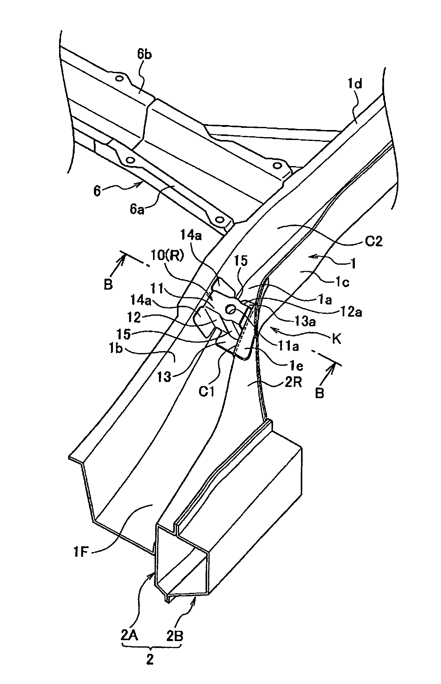
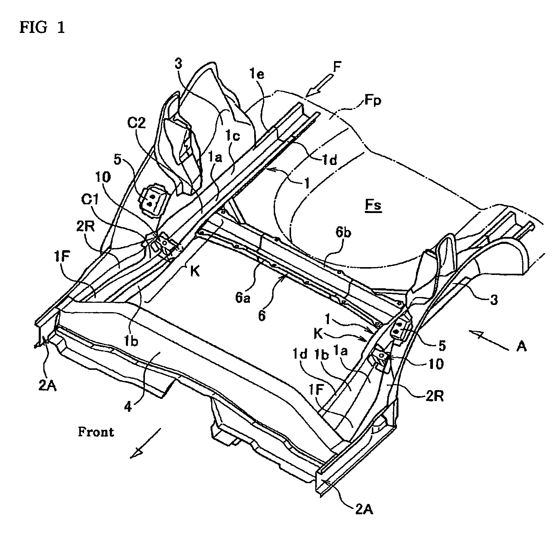
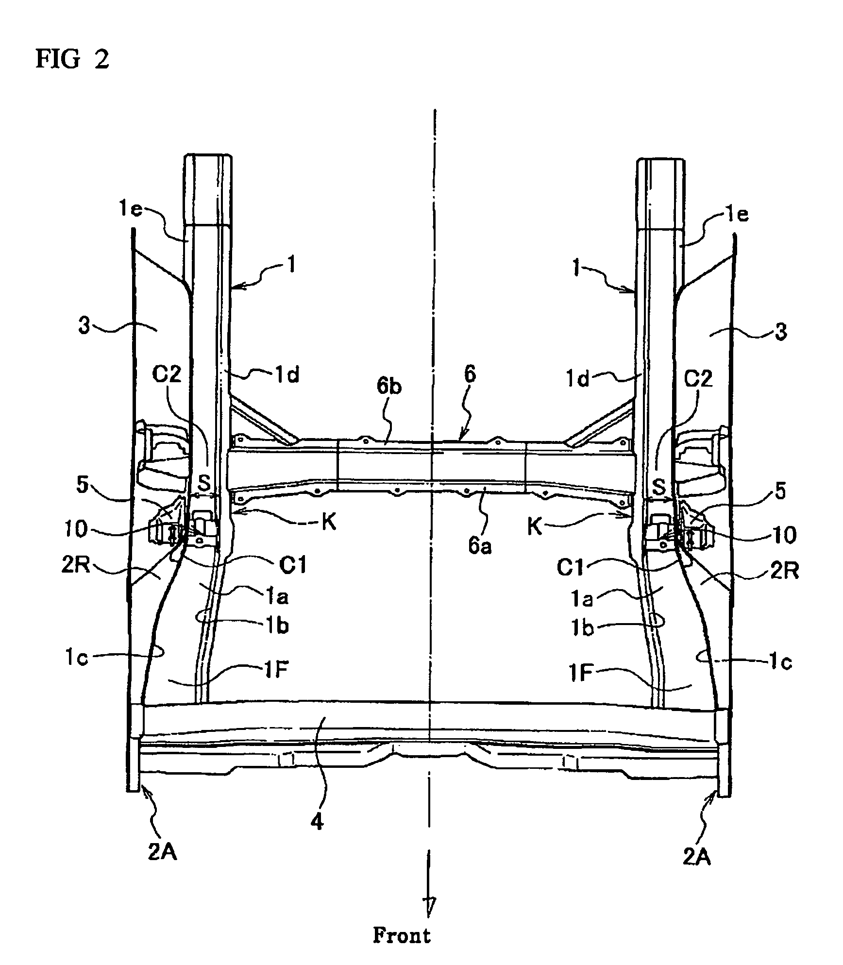
The present invention relates to a rear structure of a vehicular body that prevents the side rear member from bending upward during a rear crash while minimizing the number and weight of components. The rear structure includes a side sill, side rear members, a cross member, and reinforcements. The side rear members have a hat-shaped cross-section with a kick-up portion that is upwardly inclined towards the rear of the vehicular body. The side rear members are bonded to the side sills and extend towards the rear of the vehicular body. The cross member connects the side sills laterally across the vehicular body. The reinforcements are disposed within the side rear members and comprise a planar portion with opposing edges, a pair of side portions, and bottom flange portions. The reinforcement design helps to prevent bending of the side rear member during a rear crash.

Problems solved by technology

However, since the bulkhead alone does not provide a sufficient reinforcement, a large side member reinforcement can be further installed to the side rear members.
However, the conventional rear structure of a vehicular body is disadvantageous in that the weight of the vehicular body and the manufacturing cost inevitably increase due to the increase in the number of components.

Method used


Image

  • Rear structure of a vehicular body
  • Rear structure of a vehicular body
  • Rear structure of a vehicular body

Examples


Embodiment Construction

[0016]Exemplary embodiments of the invention will be described with reference to the accompanying figures. Like items in the figures are shown with the same reference numbers.

[0017]In embodiments of the invention, numerous specific details are set forth in order to provide a more thorough understanding of the invention. However, it will be apparent to one of ordinary skill in the art that the invention may be practiced without these specific details. In other instances, well-known features have not been described in detail to avoid obscuring the invention.

[0018]In this application, a longitudinal direction is the direction in which a vehicle incorporating the frame structure would travel, and front is the forward direction of travel of the vehicle, while rear is the backward direction of travel of the vehicle. A lateral direction is the direction in the ground plane perpendicular to the longitudinal direction. A side refers to a lateral end, and inwards means towards the lateral cen...


PUM


Abstract

A rear structure of a vehicular body has side sills disposed at lateral ends of the vehicular body. The rear structure further has side rear members having a hat-shaped cross-section and having a kick-up portion that is upwardly inclined. The side rear members are bonded to the side sills at bonded portions, and extend toward a rear of the vehicular body. The rear structure further has a cross member connecting side sills in a lateral direction across the vehicular body. The cross member is connected to each of the side sills at connected portions at a rear of the kick-up portions. The rear structure further has reinforcements having a closed cross-section in a longitudinal plane and in a lateral plane. The reinforcements are disposed in the side rear members between the bonded portions and the connected portions.

Description

CROSS-REFERENCE TO RELATED APPLICATIONS[0001]This application claims priority to Japanese Patent Application No. 2006-004799, filed on Jan. 12, 2006, the disclosure of which is incorporated by reference herein in its entirety.FIELD OF THE INVENTION[0002]The present invention relates to a rear structure of a vehicular body having a side rear member that extends from a rear portion of a side sill toward a rear portion of a vehicle.BACKGROUND ART[0003]Generally, a rear of a vehicle is provided with a pair of side rear members at both sides of the vehicle. The side rear members extend along the longitudinal direction of the vehicle. The side rear members are bonded to rear portions of inner side sills and extend from the bonded portion toward the rear portion of the vehicle so as to be attached to a rear bumper of the vehicle.[0004]The side rear members are constructed in a manner so as to increase the cross-sectional strength by providing a bulkhead (i.e., a seat installation bracket) ...

Claims


Application Information

Patent Timeline
Patent Type & Authority Patents(United States)
IPC IPC(8): B60R22/18
CPCB62D25/2027B62D25/087B62D21/15B62D25/025
Inventor YASUKOUCHI, SATOSHISATOU, HIROSHI
Owner NISSAN MOTOR CO LTD
Learn More