
Parking lock device for automatic transmission

a technology of automatic transmission and lock device, which is applied in the direction of gearing details, braking systems, transportation and packaging, etc., can solve the problems of increasing the requisite operation force of the shift lever, prone to disengage the pawl of the parking lock pole from the parking gear, and increasing the equipment cost, so as to minimize the driving force, simple configuration, and smooth operation

Inactive Publication Date: 2009-12-15
TOYOTA JIDOSHA KK
View PDF7 Cites 0 Cited by
  • Summary
  • Abstract
  • Description
  • Claims
  • Application Information

AI Technical Summary

Benefits of technology

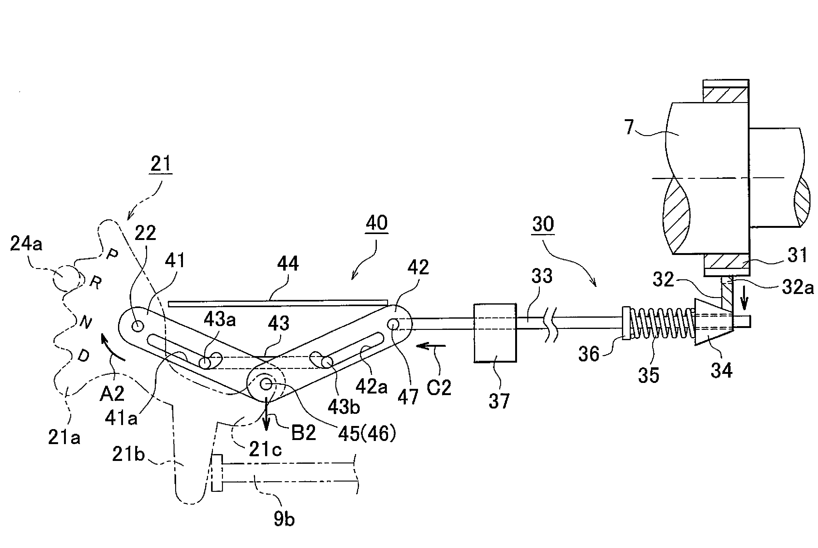
[0022]The present invention provides a parking lock device that locks the output shaft of an automatic transmission in a manner that prevents or allows rotation of the output shaft, as appropriate, and, by means of a simple configuration, minimizes the driving force that is applied by the drive lever when unlocking, and also prevents inadvertent unlocking when the output shaft is locked, thereby achieving smooth operation and enhanced reliability.

Problems solved by technology

When, in a state with the parking lock device locked, the above-mentioned forward rotation torque is input to the output shaft, this makes the pawl of the parking lock pole prone to disengage from the parking gear.
However, in that case, the driving force to be applied by the drive lever at the time of unlocking needs to be set large, resulting in an increase in the requisite operation force of the shift lever.
In contrast, although it may be possible to use assist means such as a motor for facilitating the unlocking operation, this leads to an increase in equipment cost.

Method used


Image

  • Parking lock device for automatic transmission
  • Parking lock device for automatic transmission
  • Parking lock device for automatic transmission

Examples


Embodiment Construction

[0054]An embodiment of the present invention will be described below with reference to the drawings. FIGS. 1 to 15 show an embodiment of the present invention.

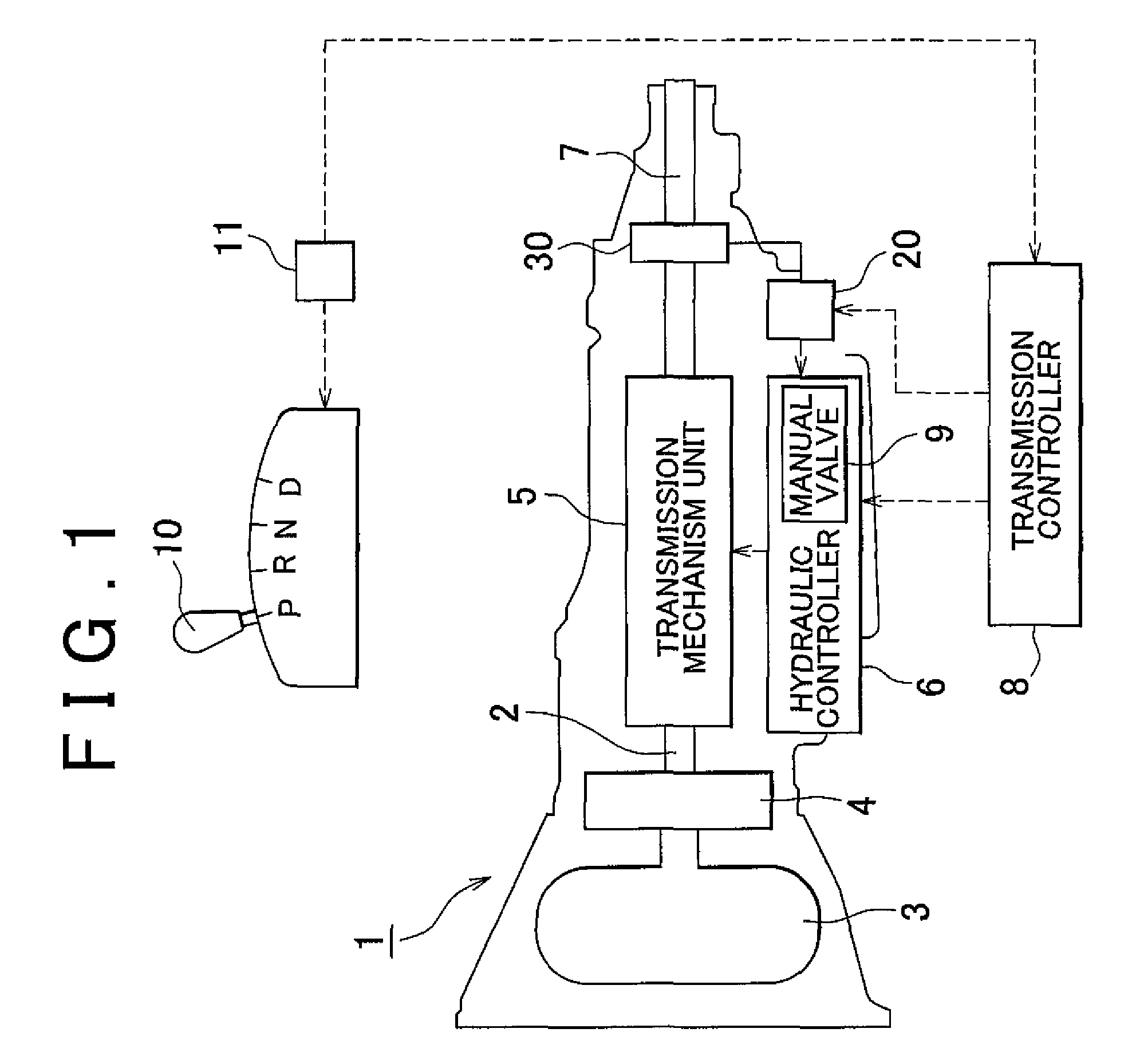
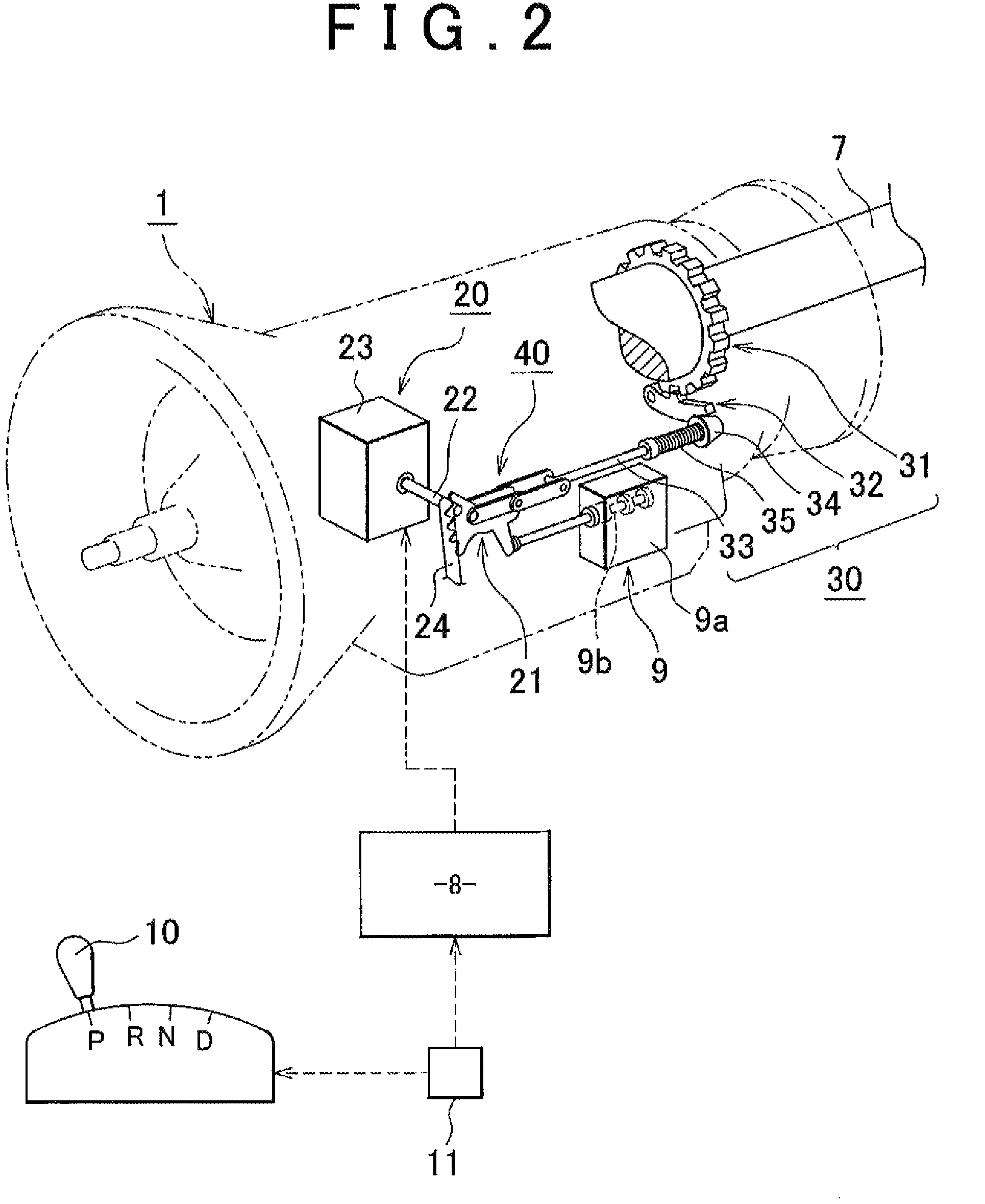
[0055]Before describing a portion to which features of the present invention are applied, an overview of an example of an automatic transmission to which a parking lock device according to the present invention is to be applied will be described with reference to FIGS. 1 and 2.

[0056]FIG. 1 is a schematic diagram of an automatic transmission to which the present invention is to be applied, and FIG. 2 is a perspective view showing a range selector and a parking lock device shown in FIG. 1.

[0057]In these figures, reference numeral 1 denotes an automatic transmission for a front-engine, rear-drive (FR) vehicle.

[0058]As shown in FIG. 1, the automatic transmission 1 mainly includes an input shaft 2, a torque converter 3, an oil pump 4, a transmission mechanism unit 5, a hydraulic controller 6, an output shaft 7, and the like. A tran...


PUM


Abstract

A parking lock device for an automatic transmission includes: a parking gear externally fixed to the output shaft; a parking lock pole displaced between a lock position, where the parking lock pole latches onto the parking gear to disable rotation of the parking gear, and an unlock position, where the parking lock disengages from the parking gear to enable rotation of the parking gear; a parking rod for displacing the parking lock pole toward and away from the parking gear; a drive lever that moves the parking rod; and a booster mechanism interposed between the parking rod and the drive lever that increases the driving force of the drive lever. Thus, the parking lock device makes the driving force applied by the drive lever when unlocking as small as possible and prevents inadvertent unlocking when in a locked state, thereby achieving smooth operation and enhanced reliability.

Description

INCORPORATION BY REFERENCE[0001]The disclosure of Japanese Patent Application No. 2007-006099 filed on Jan. 15, 2007 including the specification, drawings and abstract is incorporated herein by reference in its entirety.BACKGROUND OF THE INVENTION[0002]1. Field of Invention[0003]The present invention relates to a parking lock device for an automatic transmission for a vehicle. The parking lock device causes a pawl of a parking lock pole to latch onto a parking gear, which is externally fixed to an output shaft of an automatic transmission, to lock and prevent rotation of the output shaft, and disengages the pawl from the parking gear to unlock and allow rotation of the output shaft.[0004]2. Description of Related Art[0005]In an automatic transmission for a vehicle, generally, a parking range (P), a reverse range (R), a neutral range (N), a drive range (D), and the like are set as the selectable shift ranges.[0006]For instance, such an automatic transmission has a parking lock device...

Claims


Application Information

Patent Timeline
Patent Type & Authority Patents(United States)
IPC IPC(8): B60T1/06F16H63/34
CPCF16H63/3416F16H63/3433Y10T74/19637
Inventor NISHIMURA, NAOKI
Owner TOYOTA JIDOSHA KK
Learn More