
Navigation system

a navigation system and time-based technology, applied in navigation instruments, surveying and navigation, instruments, etc., can solve the problems of user inability to change the general navigation system, user inability to change, and difficulty in settling time points, so as to improve the freedom of time-setting

Inactive Publication Date: 2009-12-08
DENSO CORP
View PDF29 Cites 5 Cited by
  • Summary
  • Abstract
  • Description
  • Claims
  • Application Information

AI Technical Summary

Benefits of technology

[0012]The present invention has been made in consideration of the foregoing. It is therefore an object of the present invention to provide a navigation system that enhances the freedom of settling time points to determine a destination.

Problems solved by technology

However, it may often occur that a user does not conceive of a specific visit place but is sure of conditions for a place to visit.
When the destination is faraway, however, it may often occur that the user does not conceive of specific visit places or the sequence of places to visit (visit sequence) and determines visit places or the visit sequence as the user approaches the destination.
However, it is difficult for the general navigation system to change the visit place or the visit sequence in process of the route guidance.
This is because many navigation systems are designed not to accept fine-tuning operations while a vehicle is running.
First of all, the systems do not consider that the visit place or the visit sequence is surely changed.

Method used


Image

  • Navigation system
  • Navigation system
  • Navigation system

Examples


Embodiment Construction

Description of the Construction

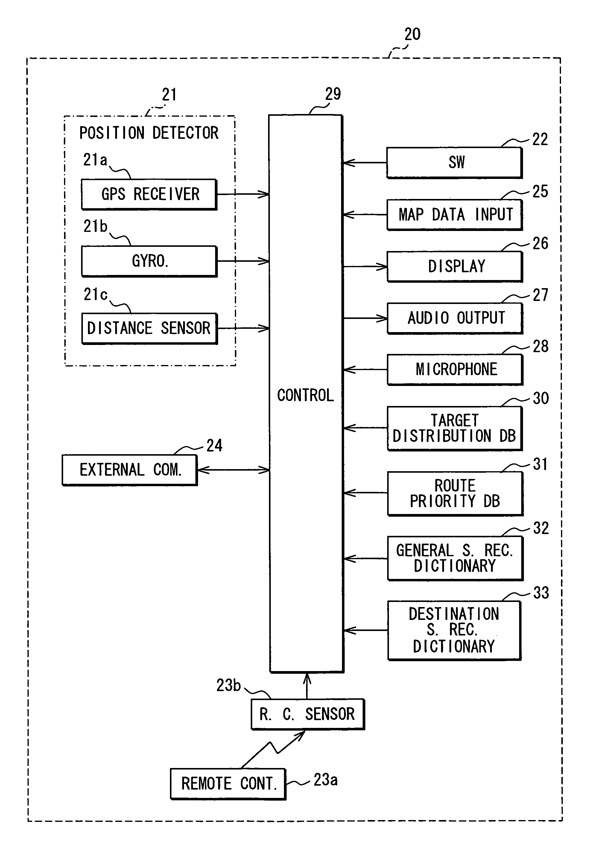
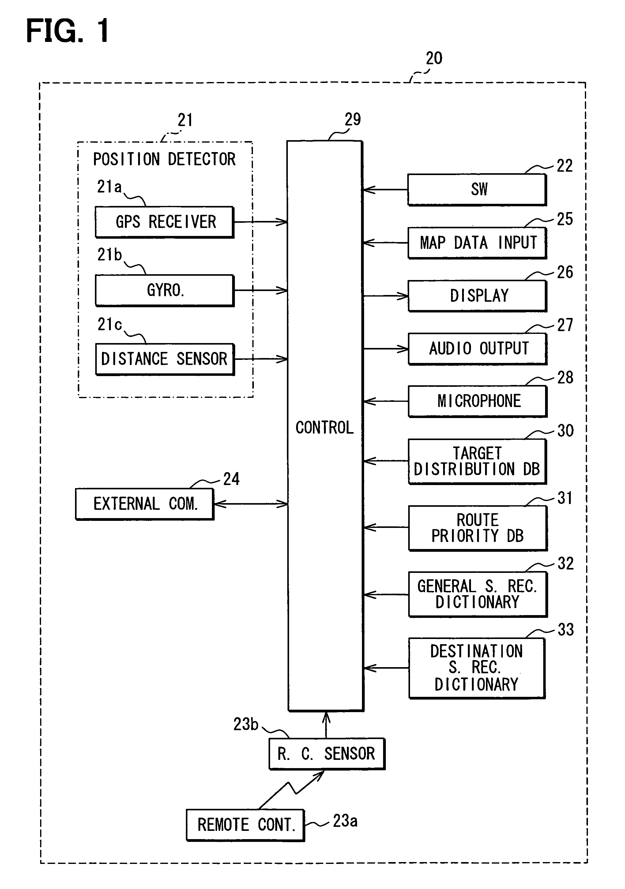
[0021]FIG. 1 is a block diagram showing a schematic construction of a navigation system 20 as an example of an embodiment according to the present invention.

[0022]The navigation system 20 in a subject vehicle includes a position detector 21, an operation switch group 22, a remote controller 23a, a remote control sensor 23b, an external communication device 24, a map data input device 25, a display unit 26, an audio output unit 27, a microphone 28, a target distribution density database 30, a route priority database 31, a general speech recognition dictionary 32, a destination specific speech recognition dictionary 33, and a control unit 29.

[0023]The position detector 21 detects a current position of the vehicle or navigation system 20 itself. The operation switch group 22 allows a user to supply various instructions, functioning as means for accepting instructions from a user. Similarly to the operation switch group 22, the remote controller 23a can en...


PUM


Abstract

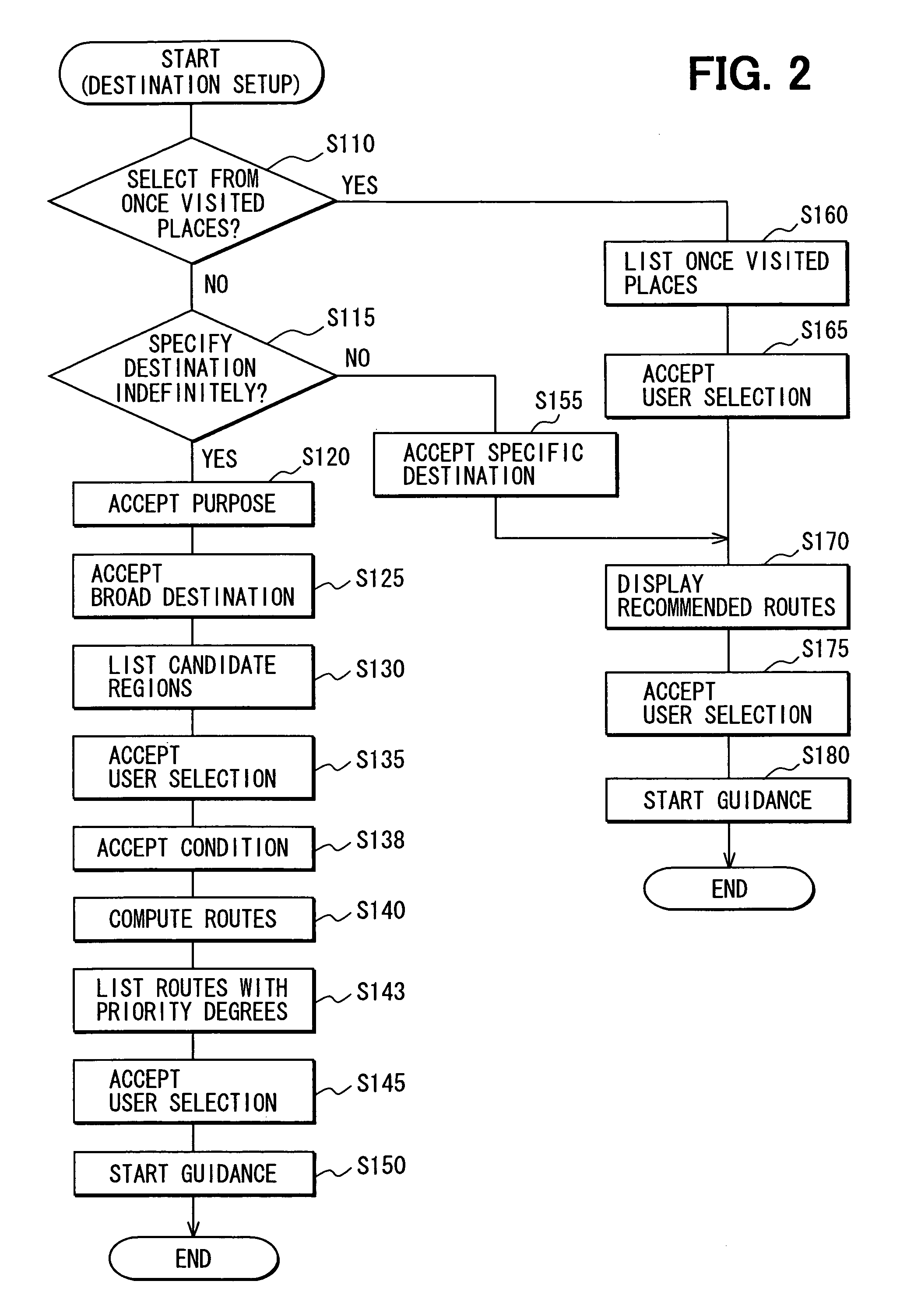
There is a need for providing a navigation system that enhances the freedom of settling time points to determine a destination. The system prompts a user to input only information needed for determining a target region (e.g., a region including several tourist spots or a region including several ski resorts) at a departure time. The system prompts a user to input information needed for determining a specific destination (e.g., a specific tourist spot, or a specific ski resort) halfway through the target region. Accordingly, the user need not determine a specific destination at the departure time.

Description

CROSS REFERENCE TO RELATED APPLICATIONS[0001]This application is based on and incorporates herein by reference Japanese Patent Application No. 2005-242930 filed on Aug. 24, 2005.FIELD OF THE INVENTION[0002]The present invention relates to a navigation system for providing route guidance.BACKGROUND OF THE INVENTION[0003]Presently, the well-known navigation system necessitates a user to specify a destination in a pinpoint manner. That is, the user needs to specify a destination by locating an intended point on a map displayed on a display unit, selecting an address or a facility from a menu, or specifying a place stored in memory.[0004]However, it may often occur that a user does not conceive of a specific visit place but is sure of conditions for a place to visit. For this purpose, there is available a navigation system that allows a user to supply conditions for a place to visit and retrieves and proposes visit places satisfying the conditions.[0005]For example, the technology descr...

Claims


Application Information

Patent Timeline
Patent Type & Authority Patents(United States)
IPC IPC(8): G01C21/30G01C21/32G08G1/123
CPCG01C21/3461G01C21/3617G01C21/3614
Inventor HAGIWARA, KAZUHIKO
Owner DENSO CORP
Learn More