Techniques for ensuring synchronized processing at remote fiber channel and fiber connectivity networks

a technology of fiber connectivity and remote fiber channel, applied in the direction of multiplex communication, time-division multiplex, electrical equipment, etc., can solve the problems of limiting early optical networks, unable to mesh directly with these larger distance optical protocols, and many san protocols are not compatible with them

Inactive Publication Date: 2009-12-08
CISCO TECH INC
View PDF9 Cites 16 Cited by
  • Summary
  • Abstract
  • Description
  • Claims
  • Application Information

AI Technical Summary

Problems solved by technology

Because of attenuation of light intensity in optical cable, however, early optical networks were confined to providing high bandwidth connections (“wide pipes”) into high volume data storage devices over limited-distances.
One fallout of recent man-made and natural disasters is the recognition that such valuable data is best redundantly distributed at widely geographically spaced locations.
Several of the SAN protocols however, do not mesh directly with these larger distance optical protocols.
For links of thousands of miles, this delay can be substantial (over 3 ms).
The procedures and buffer sizes designed for the short haul are wasteful of bandwidth on the longer haul.
The original FC Protocol standard, however, did not anticipate this signaling need and does not provide a field in FC frames to specify the distance extension mode used.
While suitable in some instances, there are disadvantages with these approaches.
One disadvantage arises because the GFP header is typically processed in hardware configured as a GFP chip.
Replacement of multiple GFP chips is costly and can be prohibitive for organizations that have tens to hundreds of FC edge nodes already deployed with the older GFP chips.

Method used


Image

  • Techniques for ensuring synchronized processing at remote fiber channel and fiber connectivity networks
  • Techniques for ensuring synchronized processing at remote fiber channel and fiber connectivity networks
  • Techniques for ensuring synchronized processing at remote fiber channel and fiber connectivity networks

Examples


Embodiment Construction

[0027]Techniques are described for ensuring synchronized processing at remote Fiber Channel networks. In the following description, for the purposes of explanation, numerous specific details are set forth in order to provide a thorough understanding of the present invention. It will be apparent, however, to one skilled in the art that the present invention may be practiced without these specific details. In other instances, well-known structures and devices are shown in block diagram form in order to avoid unnecessarily obscuring the present invention.

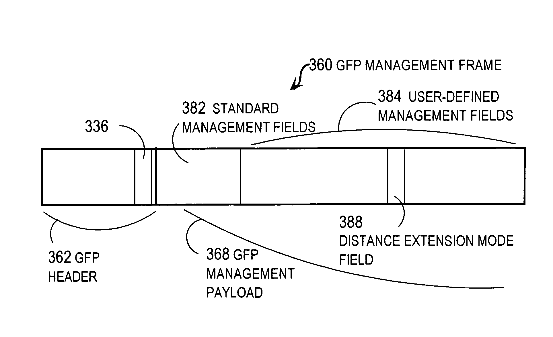
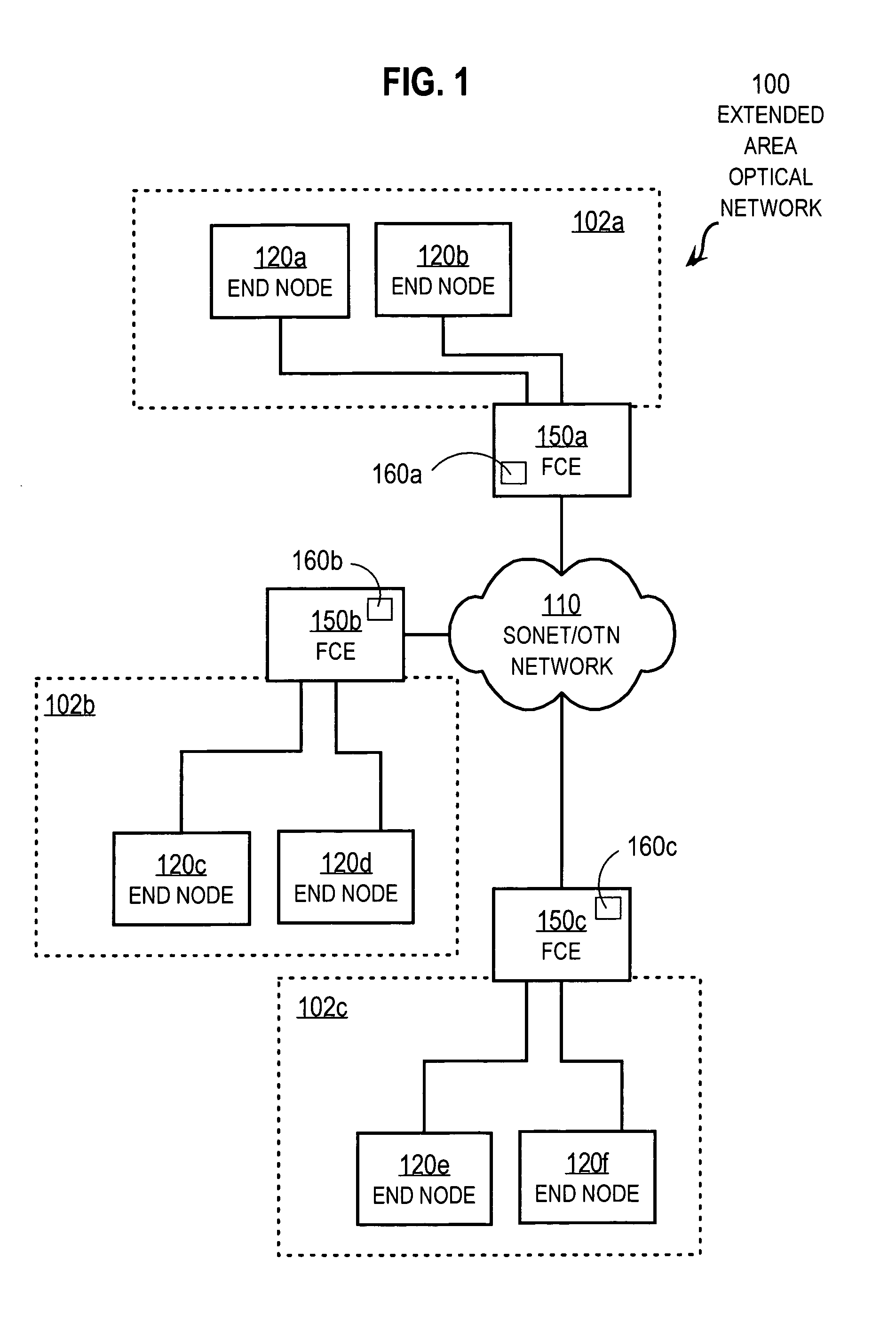
[0028]Illustrated embodiments of the invention are described in the context of ensuring synchronized Distance Extension (DE) mode processing at remote Fiber Channel (FC) edge nodes using Generic Framing Procedure (GFP) to transport data across an extended area optical transport network using SONET over OTN. However, the invention is not limited to this context. In other embodiments other current or future FC processing options at remot...


PUM


Abstract

Techniques described use Generic Framing Procedure (GFP) to transport data across an optical transport network between near and far Fiber Channel (FC) or Fiber Connectivity (FICON) local area optical networks. Each FC / FICON edge node (FCE) on an edge of the optical transport network has multiple modes for processing FC / FICON frames transported across the optical transport network. The techniques include receiving, at a near FCE from a far FCE, a GFP control plane message that includes a mode field that holds data that indicates a far mode, wherein the far mode is used at the far FCE. It is determined whether a near mode used by the near FCE matches the far mode based on the mode field. If it is determined that they do not match, then an alert is caused. These techniques allow software to utilize existing GFP chips in FCE that use optional processing, such as distance extension.

Description

BACKGROUND OF THE INVENTION[0001]1. Field of the Invention[0002]The present invention relates to communicating between Fiber Channel (FC) or Fiber Connectivity (FICON) protocol networks separated by Metro Area Network (MAN) or other Wide Area network (WAN) using the Generic Framing Procedure (GFP); and, in particular, to using GFP control packets to coordinate the use of distance extension at the separated FC / FICON networks.[0003]2. Description of the Related Art[0004]Networks of general purpose computer systems and special devices connected by external communication links are well known. The networks often include one or more network devices that facilitate the passage of information between the computer systems and special devices. A network node is a network device or computer system or other special device connected by the communication links.[0005]Information is exchanged between network nodes according to one or more of many well known, new or still developing protocols. In th...

Claims


Application Information

Patent Timeline
IPC IPC(8): H04J3/00
CPCH04J3/1617H04J2203/0082H04J2203/0066H04J3/1658
Inventor GAO, FANGYAO, GONGYUANSINGHAL, RAVI
Owner CISCO TECH INC
Why Eureka
Try Eureka