Antenna using proximity-coupled feed method, RFID tag having the same, and antenna impedance matching method thereof
a proximity-coupled feed and antenna technology, applied in the direction of antennas, antenna details, electrically short antennas, etc., can solve the problems of reducing the service life of the rfid reader, affecting the integrity of the view, and the conventional method of using the additional matching circuit has a drawback in the view of integrity and manufacturing costs
- Summary
- Abstract
- Description
- Claims
- Application Information
AI Technical Summary
Benefits of technology
Problems solved by technology
Method used
Image

Examples
first embodiment
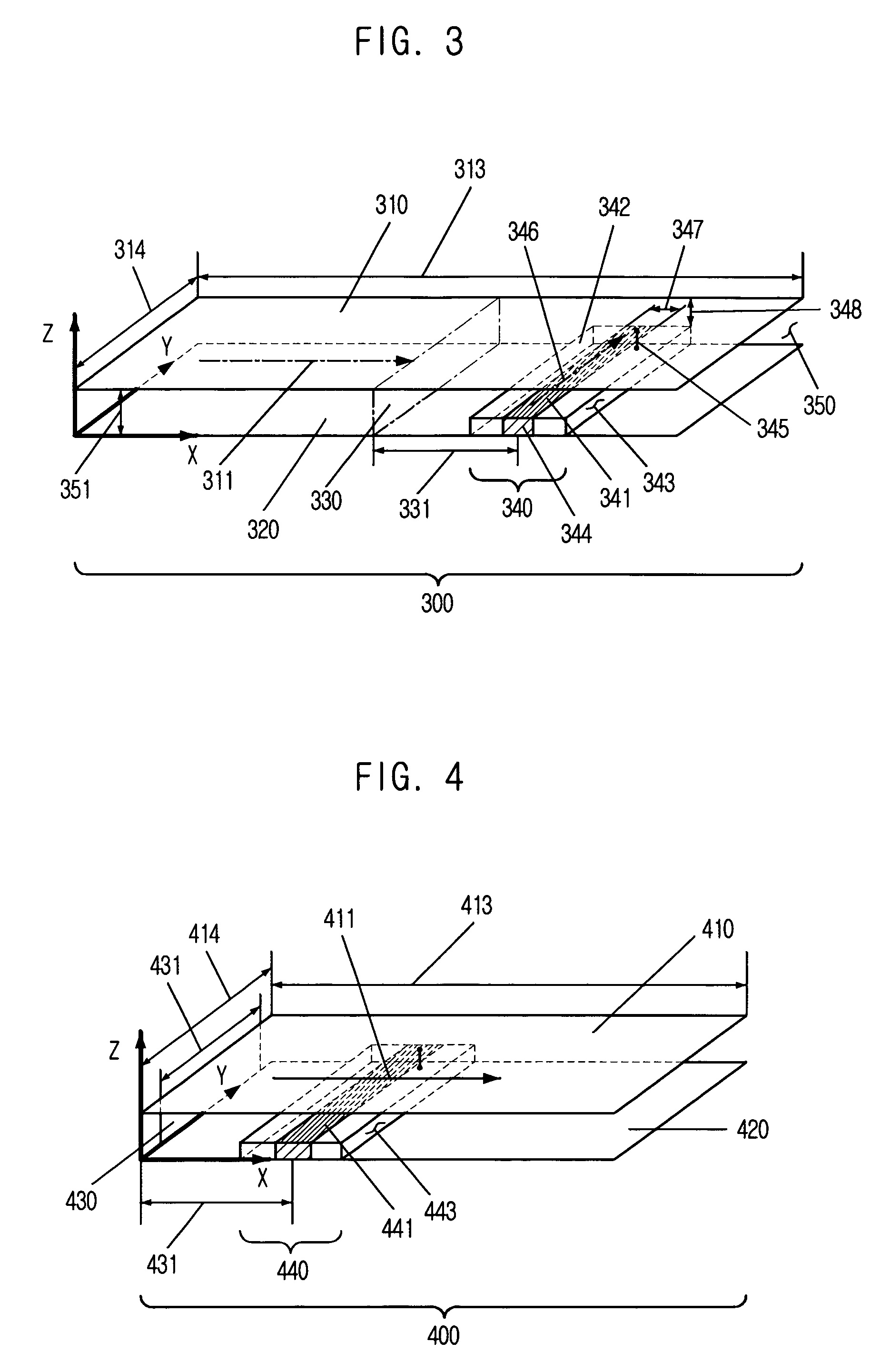
[0028]FIG. 3 is a view illustrating a tag antenna 300 in accordance with the present invention.
[0029]Referring to FIG. 3, the tag antenna 300 according to the present embodiment includes a rectangular radiation patch 310 and a ground plate 320 disposed to be parallel from the radiation patch 310. The radiation patch 310 is proximity-coupled to a microstrip feed line 341. The direction 346 of the microstrip feed line 341 is perpendicular to the resonant length direction 311 of the radiation patch 310. That is, as shown in FIG. 3, if the resonant length direction of the radiation patch 310 is a direction x, the direction 346 of the feed line 341 is controlled to be in a direction y. The radiation patch 310 and the ground plate 320 are separated each other at a constant distance 351 in parallel, and the predetermined portion or the entire of the radiation patch 310 and the ground plate 320 are filled with a predetermined dielectric material 350 including air. The resonant frequency of ...
second embodiment
[0037]FIG. 4 is a view of a tag antenna 400 using a proximity coupled feed method in accordance with the present invention.
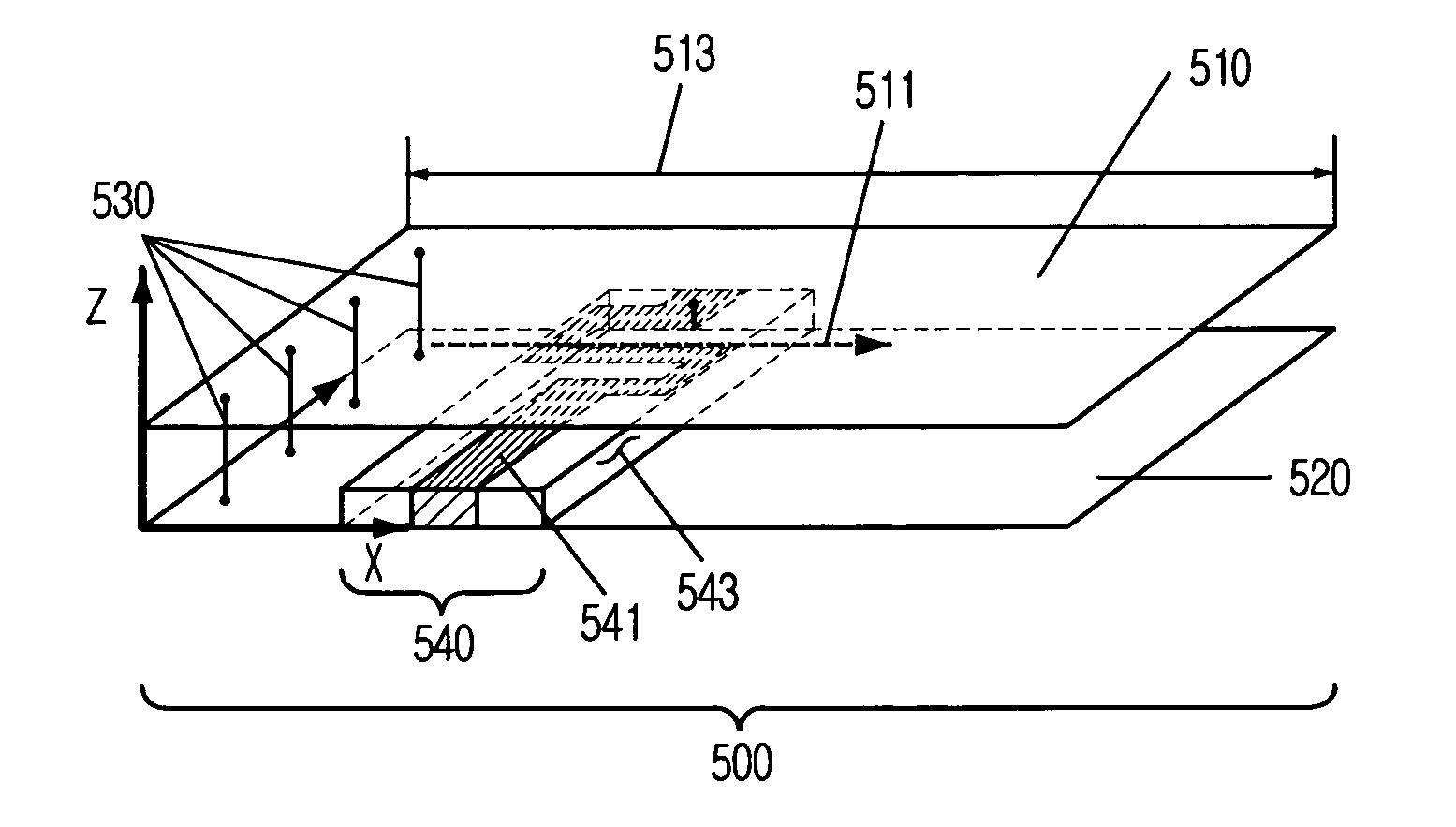
[0038]Referring to FIG. 4, the tag antenna 400 according to the second embodiment includes a radiation patch 410, a ground plate 420 and a shorting plate 430. In the tag antenna 400 according to the second embodiment, the length of the radiation patch 413 is reduced by shorting the radiation patch 410 and the ground late 430 through disposing the shorting plate 430 between the radiation patch 410 and the ground plate 420. The shorting plate 430 is disposed in a perpendicular direction, which is a direction y, form the resonant length direction 411 of the radiation patch 410 at one side corner of the radiation patch 410. The width 431 of the shorting plate may be different from the width 414 of the radiation patch. As shown in FIG. 4, the equivalent impedance between the radiation patch 410 and the ground plate 420 becomes about 0Ω. Therefore, the resistance comp...
fourth embodiment
[0042]FIG. 6 is a view showing a tag antenna 600 using a proximity coupled feed method in accordance with the present invention. Unlike from the other antennas shown in FIGS. 3 to 5, the ground side of the feeder 640 is shorted from the radiation patch 610 in a DC manner, or shorted through the capacitive coupling in an AC manner in the tag antenna 600 of FIG. 6. Also, the radiation patch 610 may be shared as the ground side of the feeder. As shown in FIG. 6, the ground plate 620 is proximity-coupled to the feed line 641. The operations and the effects of the present invention described with reference to FIGS. 3 to 5 are identically applied into the tag antenna 600 of FIG. 6.
[0043]As described above, the microstrip feed line is disposed between the radiation patch and the ground plate to be perpendicular from the resonant length direction of the radiation patch so as to be proximity coupled to the radiation patch in the antenna according to the present invention. Therefore, the resi...
PUM
 Abstract
Description
Claims
Application Information
 - R&D
- Intellectual Property
- Life Sciences
- Materials
- Tech Scout
- Unparalleled Data Quality
- Higher Quality Content
- 60% Fewer Hallucinations
Browse by: Latest US Patents, China's latest patents, Technical Efficacy Thesaurus, Application Domain, Technology Topic, Popular Technical Reports.
© 2025 PatSnap. All rights reserved.Legal|Privacy policy|Modern Slavery Act Transparency Statement|Sitemap|About US| Contact US: help@patsnap.com