Eureka AIR delivers breakthrough ideas for toughest innovation challenges, trusted by R&D personnel around the world.

Contact lens having a uniform horizontal thickness profile

a contact lens and horizontal thickness technology, applied in the field of contact lenses, can solve the problems of insufficient interaction with the contact lens, high variable orientation and/or discomfort, and undesired interaction

Inactive Publication Date: 2009-12-08
COOPERVISION INT LTD
View PDF188 Cites 1 Cited by
  • Summary
  • Abstract
  • Description
  • Claims
  • Application Information

AI Technical Summary

Benefits of technology

[0026]The demolded contact lens member may be the final contact lens. However, the demolded contact lens member may be hydrated or further hydrated to form the final contact lens with a rounded edge surface. One important advantage of the present invention is that the present contact lenses preferably do not require post-formation (after being molded) processing to alter the rounded configuration of the outer peripheral edge surface of the contact lens member or contact lens. Post-formation processing such as demolding, hydration, sterilization, packaging and the like of the contact lens or contact lens member does not alter this rounded edge surface configuration.
[0027]The portion of the back surface tool that forms the lens periphery is convex in form, preferably having a radius of at least about 0.05 mm or larger. Correspondingly, the first mold section formed by the tooling insert has a concave outer edge surface. It will be appreciated by those skilled in the art that both the tooling insert and the mold section formed thereby, in accordance with the present invention, are significantly different in form from conventional back surface tooling inserts and conventionally produced back surface mold sections.
[0028]Preferably, in accordance with the present invention, a junction angle formed between the assembled first and second mold sections, on the lens side of the lens-shaped cavity, is at least about 100 degrees, more preferably in the range of about 100 degrees to about 170 degrees.
[0029]The present invention further provides a tool, preferably a back surface tool, useful for cast molding a contact lens, for example, a contact lens having a rounded peripheral edge surface in making a mold section. In accordance with this embodiment of the invention, the tool generally comprises an insert adapted to be placed in a molding apparatus in forming a first mold section, specifically a back surface mold section, having a negative impression of a surface of the tool. To form the rounded edge surface of the final lens product, the surface of the tool includes a first surface portion in the general shape of a lens face, preferably a posterior lens face, of a contact lens, and a second surface portion defining a convex curved outer peripheral edge surface of the insert. The second surface portion may be defined by a continuous curve with a radius of curvature of about 0.05 mm. Alternatively, the second surface portion may be defined by a series of small flats, or a combination of small flats and curves, which approximate a convexly curved surface.
[0030]In another aspect of the present invention, a mold useful in producing, e.g., cast molding, a contact lens, preferably, a contact lens with a rounded edge surface, is provided. The mold generally comprises a first mold section having a surface in a general shape of a negative of a lens face, preferably a posterior lens face, of a contact lens to be cast molded using the mold and a concave outer edge surface, and a second mold section having a surface in a general shape of a negative of an opposing lens face, preferably an anterior lens face of the contact lens to be cast molded using the mold. The first mold section and the second mold section are adapted to be assembled together, for example, in a conventional manner, to define a cavity, in which is formed a fully cast molded, rounded edge contact lens or contact lens member in accordance with the present invention.
[0031]In a further aspect of the present invention, fully cast molded contact lenses having rounded peripheral edge surfaces are provided. Such contact lenses may be produced using the methods, tools and molds described herein.

Problems solved by technology

The principal limitation of existing toric contact lens designs is that orientation is highly variable and / or uncomfortable, for a given design, between individual toric lens wearers.
Patient factors such as blink characteristics and ocular parameters such as eyelid, corneal, and conjuctival shape and anatomy may result in undesired interaction (for example, asymmetry) or insufficient interaction with the contact lens.
However, many of the problems associated with prior art mechanisms may be attributed to problems with failure of the stabilization mechanism to maximize eyelid interaction and reduce the variability of lens orientation between individuals.

Method used


Image

  • Contact lens having a uniform horizontal thickness profile
  • Contact lens having a uniform horizontal thickness profile
  • Contact lens having a uniform horizontal thickness profile

Examples


Embodiment Construction

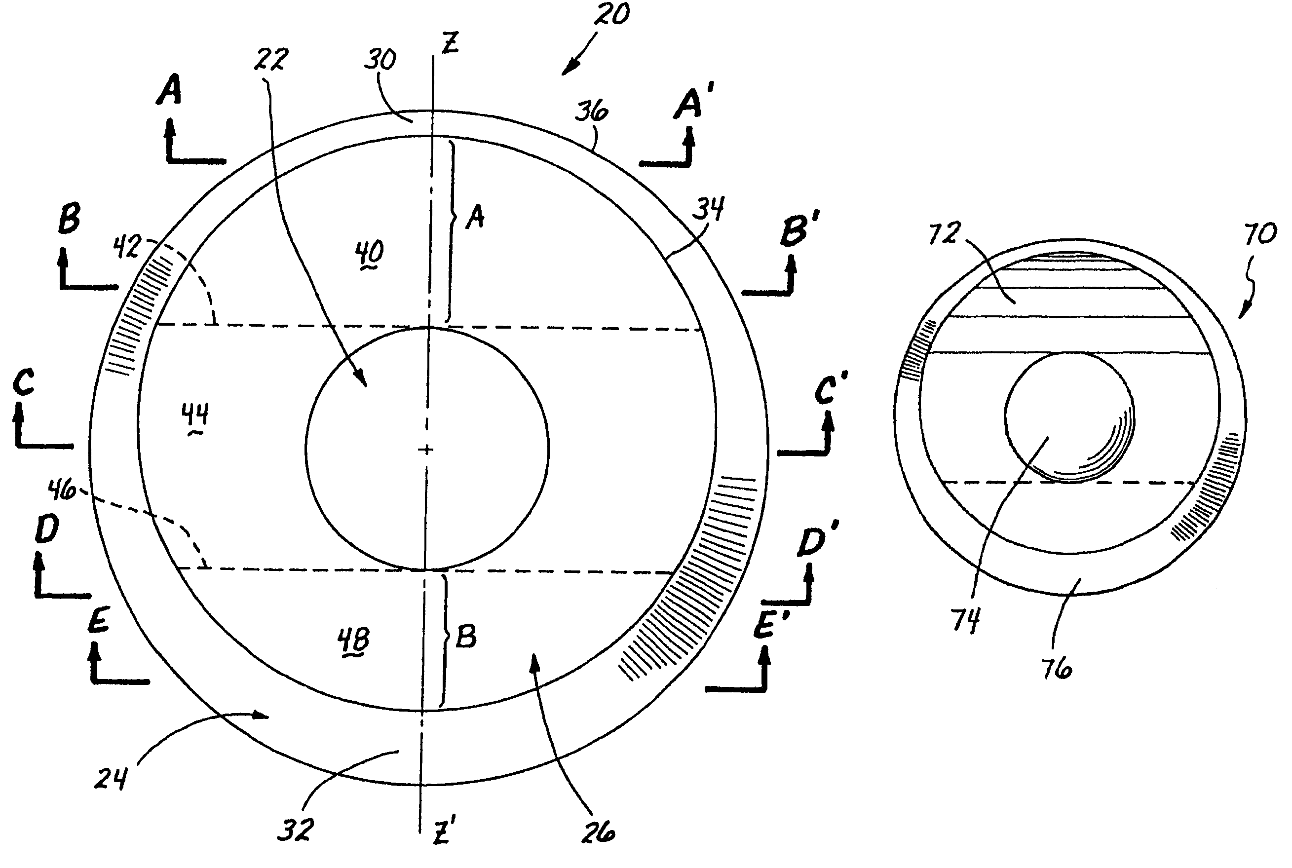
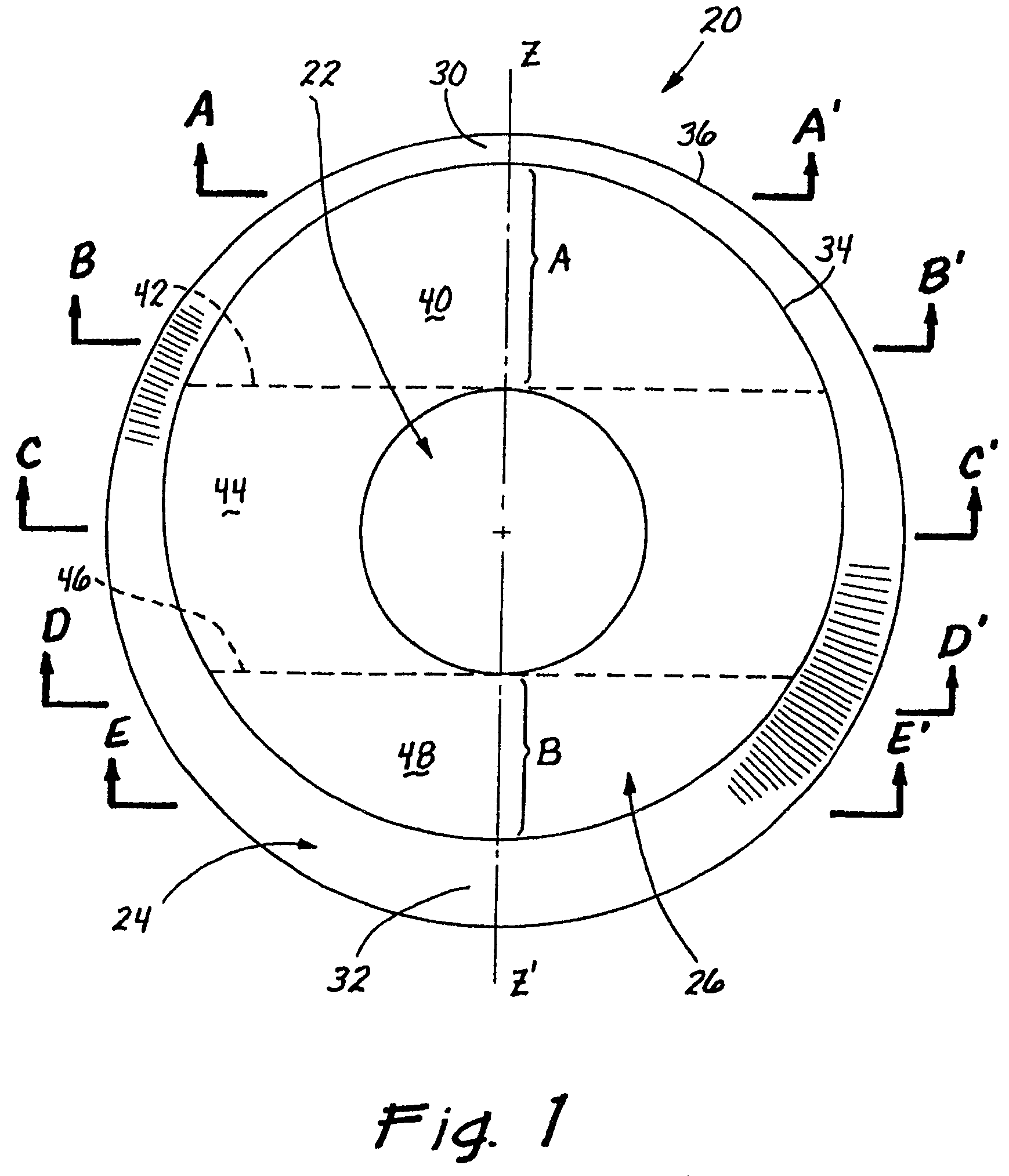
[0048]The present invention provides stabilized contact lenses, especially contact lenses having a cylindrical correction for astigmatism. More broadly, the present invention provides contact lenses having elevated surfaces thereon that interact with the blinking action of the eyelids to rotationally stabilize the lens. The rotational stability is useful for any contact lens that is non-axi-symmetric. For example, the rotational orientation of toric lenses or multifocal lenses must be maintained for proper correction. It should be understood, however, that rotational stability may also be desirable for other specialized lenses.

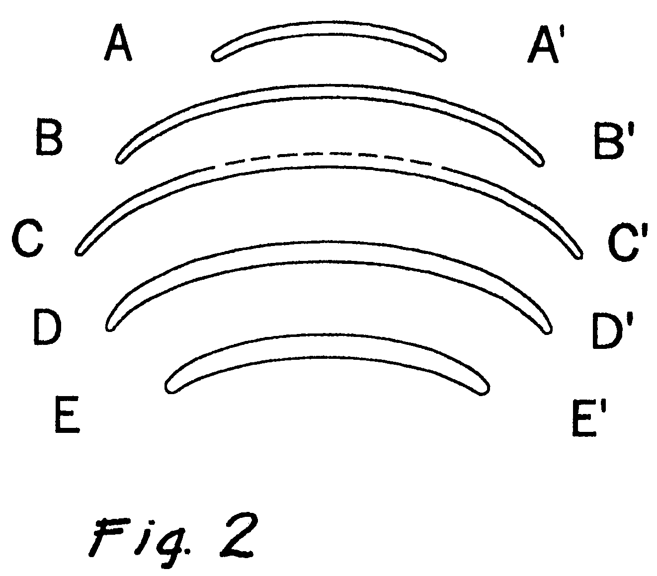
[0049]In the following description, a number of surfaces and thicknesses of the contact lenses of the present invention will be described with reference to schematic elevational views of the lenses, in that the lenses have been flattened. Contact lenses typically possess an underlying spherical curvature, with the anterior face being convex, and the posterior ...


PUM


Abstract

A contact lens having a rotational stabilization mechanism thereon, such as prism ballast, and a thickness profile that reduces the torque imparted on the lens by the action of the eyelids, especially for stabilizing toric lenses. The prism ballast is provided on one or more portions of the anterior face of the lens such that the lens body has a uniform thickness of within 10% along horizontal cross-sections. The anterior face of the lens may be segregated into a peripheral zone, an inner zone circumscribed by the peripheral zone, and a central optic zone. The prism ballast portion is provided within the inner zone, which may be further subdivided into a superior portion, an intermediate portion proximate the optic zone, and an inferior portion. The ballast portion increases in thickness along a superior-inferior line parallel to a vertical meridian, and has a substantially uniform thickness perpendicular thereto. The peripheral zone may be tapered, and have a rounded edge. The rate of thickness change across any portion of the peripheral zone is less than about 250 μm / mm.

Description

CROSS-REFERENCE TO RELATED APPLICATIONS[0001]This application is a continuation-in-part of application Ser. No. 11 / 188,071, filed Jul. 22, 2005, which is a continuation of application Ser. No. 10 / 827,168, filed Apr. 19, 2004, now U.S. Pat. No. 6,971,746, which is a continuation of application Ser. No. 10 / 171,718, filed Jun. 14, 2002, now U.S. Pat. No. 6,857,740, which is a continuation of application Ser. No. 09 / 818,244, filed Mar. 27, 2001, now U.S. Pat. No. 6,467,903, which claims the benefit of U.S. provisional application No. 60 / 193,493, filed Mar. 31, 2000.[0002]This application is a continuation-in-part of application Ser. No. 11 / 127,584, filed May 11, 2005, which is a continuation of application Ser. No. 10 / 171,927, filed Jun. 14, 2002, now U.S. Pat. No. 6,923,538, which is a continuation of application Ser. No. 09 / 611,768, filed Jul. 6, 2000, now U.S. Pat. No. 6,431,706.[0003]The disclosure of each of these applications is incorporated in its entirety herein by reference.BAC...

Claims


Application Information

Patent Timeline
Patent Type & Authority Patents(United States)
IPC IPC(8): G02C7/04
CPCG02C7/048G02C7/04
Inventor BACK, ARTHURDEAN, GREGG A.
Owner COOPERVISION INT LTD
Why Eureka
Eureka Blog
Learn More