
Charging system and method

a charging system and charging method technology, applied in the direction of dc source parallel operation, ac network voltage adjustment, transportation and packaging, etc., can solve the problems of occupying valuable space in the portable device, adding to the expense of the device or the charger

Inactive Publication Date: 2009-12-01
GOOGLE TECH HLDG LLC
View PDF3 Cites 11 Cited by
  • Summary
  • Abstract
  • Description
  • Claims
  • Application Information

AI Technical Summary

Benefits of technology

The present invention is about a method and system for charging a battery. The method involves monitoring the input power supply signal to determine when it reaches certain thresholds, and then controlling a charging switch to control the flow of power to the battery. This allows for efficient charging of the battery while reducing the need for a large capacitor. The system includes a coil, charging switch, and controller for carrying out this method. The technical effects of this invention include improved battery charging efficiency and reduced circuit size.

Problems solved by technology

Unfortunately, the capacitor must be relatively large to maintain the necessary voltage, which takes up valuable space in the portable device and adds to the expense of the device or charger.

Method used


Image

  • Charging system and method
  • Charging system and method
  • Charging system and method

Examples


Embodiment Construction

[0015]While the specification concludes with claims defining the features of the invention that are regarded as novel, it is believed that the invention will be better understood from a consideration of the following description in conjunction with the drawing figures, in which like reference numerals are carried forward.

[0016]Referring to FIG. 1, a charging system 100 for charging a battery 110 is shown. The charging system 100 can include a power source 112, an inductor I1 having a first coil 114 and a second coil 116, a rectifier 118, a capacitor C1, a resistor R1, a resistor R2 and a controller 120. The charging system 100 can further include a charging switch 122 coupled to the battery 110, a second switch 124 and a backlighting circuit 126 in which the second switch 124 is coupled to the backlighting circuit 126. The controller can control the operation of the charging switch 122 and the second switch 124.

[0017]All or portions of the inductor I1, the rectifier 118, the capacit...


PUM


Abstract

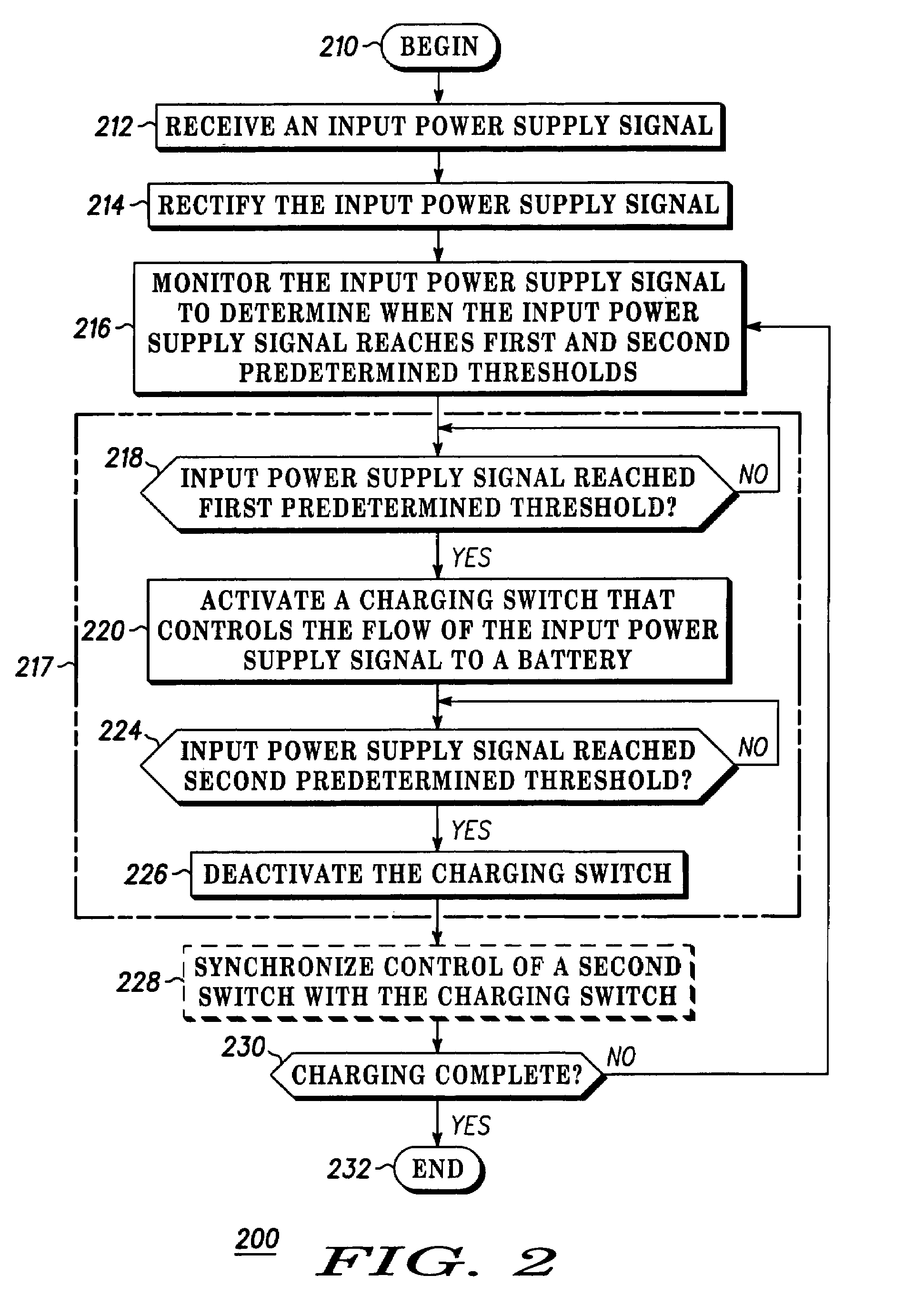
The invention concerns a method (200) and system (100) for charging a battery (110). The method includes the steps of receiving (212) an input power supply signal (300), monitoring (216) the input power supply signal to determine when the input power supply signal reaches first and second predetermined thresholds (314, 316) and in response to the monitoring step, selectively controlling (217) a charging switch (122) that controls the flow of the input power supply signal to the battery. The controlling step can include activating (220) the charging switch when the input power supply signal reaches the first predetermined threshold and deactivating (226) the switch when the input power supply signal reaches the second predetermined threshold.

Description

CROSS REFERENCE TO RELATED APPLICATIONS[0001](Not Applicable)BACKGROUND[0002]1. Technical Field[0003]This invention relates in general to charging systems and more particularly, to charging systems that rely on rectified charging currents.[0004]2. Description of the Related Art[0005]In today's marketplace, portable electronic devices have become ubiquitous. Because they are portable, nearly all of these devices include rechargeable batteries as their power supply. Such portable devices are equipped with a charger, which can be incorporated in the device or can be a stand-alone unit that can receive the portable device. In either embodiment, the charger typically receives an AC input signal and converts this signal to a DC signal, which is then fed to the cells of the battery. These types of chargers generally include a rectifier that rectifies the incoming AC signal.[0006]A rectified signal, however, will have a series of voltage peaks and valleys. A capacitor is typically provided ...

Claims


Application Information

Patent Timeline
Patent Type & Authority Patents(United States)
IPC IPC(8): H02J7/00H02J7/14H02J1/10H04M1/00H02J7/02H02J7/04
CPCH02J7/042H02J7/025H02J7/007H02J7/04H02J50/10
Inventor PATINO, JOSEPHPULIDO, MARCOSIMPSON, RUSSELL L.
Owner GOOGLE TECH HLDG LLC
Learn More