
Method for the operation of a hybrid drive train in a motor vehicle

a hybrid drive and motor vehicle technology, applied in hybrid vehicles, gearing, vehicle sub-unit features, etc., can solve the problems of loss of propulsion associated with electric motors, no torque can be transferred to drive wheels, and perceived as detrimental by users of motor vehicles, so as to avoid loss of propulsion force

Inactive Publication Date: 2009-12-01
SCHAEFFLER TECH AG & CO KG
View PDF9 Cites 29 Cited by
  • Summary
  • Abstract
  • Description
  • Claims
  • Application Information

AI Technical Summary

Benefits of technology

[0010]Thus, it is the object of the invention to provide a method as described supra, which avoids a loss of propulsion force when shifting a second gear with the electric motor previously engaged for propulsion.
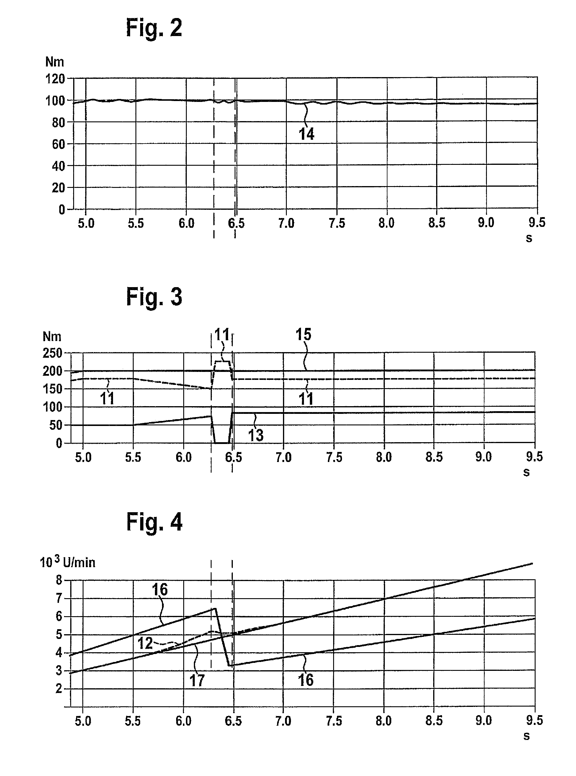
[0017]Before the gear change is begun, thus the torque transferred through the first clutch is reduced through partial opening of the first clutch. Thus, the speed of the internal combustion engine is slightly increased, so that additional kinetic energy is stored in the internal combustion engine. The reduction of the total torque transferred to the transmission output shaft through the first clutch is compensated by a respective increase of the torque of the electric motor. Thus, the acceleration of the motor vehicle can be kept approximately constant in spite of the reduced clutch moment of the first clutch. As soon as a sufficient slippage reserve exists, the torque of the electric motor is reduced to zero. The reduction is compensated by a respective increase of the torque transferred by the first clutch. Thus, the slippage at the first clutch is reduced. Thus, the acceleration of the motor vehicle can be kept constant instead of the lacking drive torque of the electric motor. After the second gear has been shifted and synchronized, torque is transferred again by the electric motor to the transmission output shaft. The torque transferred through the first clutch and possibly through the second clutch from the internal combustion engine to the transmission output shaft is reduced accordingly. Thus, the full acceleration force is maintained in boost operation of the hybrid drive train during the shifting process without interruption.
[0026]It is advantageous, when the torque of the electric motor is adapted to the clutch slippage of the first clutch, so that torque transmitted through the first clutch is maintained approximately constant while the clutch slippage is build-up. The motor vehicle can then be accelerated in an even smoother manner.
[0027]The slippage of the first clutch is preferably reduced, so that the torque transmitted to the transmission output shaft remains approximately constant from the beginning of the reduction of the torque applied by the electric motor until the end of the closing process of the second clutch. Also, by this measure, a smooth acceleration of the motor vehicle is facilitated during the shifting process.
[0028]It is advantageous when the torque of the electric motor is increased or reduced in a ramp profile. The slippage in the first clutch can then be increased and decreased smoothly.

Problems solved by technology

The method has the disadvantage that during a gear change on the second transmission input shaft, thus when shifting from gear “2” to gear “4”, and from gear “4” to gear “6”, no torque can be transferred from the electric motor to the drive wheels, since the partial transmission formed by the second gears is in neutral position for the moment.
The loss of propulsion associated therewith is perceived as detrimental by the users of the motor vehicle.

Method used


Image

  • Method for the operation of a hybrid drive train in a motor vehicle
  • Method for the operation of a hybrid drive train in a motor vehicle
  • Method for the operation of a hybrid drive train in a motor vehicle

Examples


Embodiment Construction

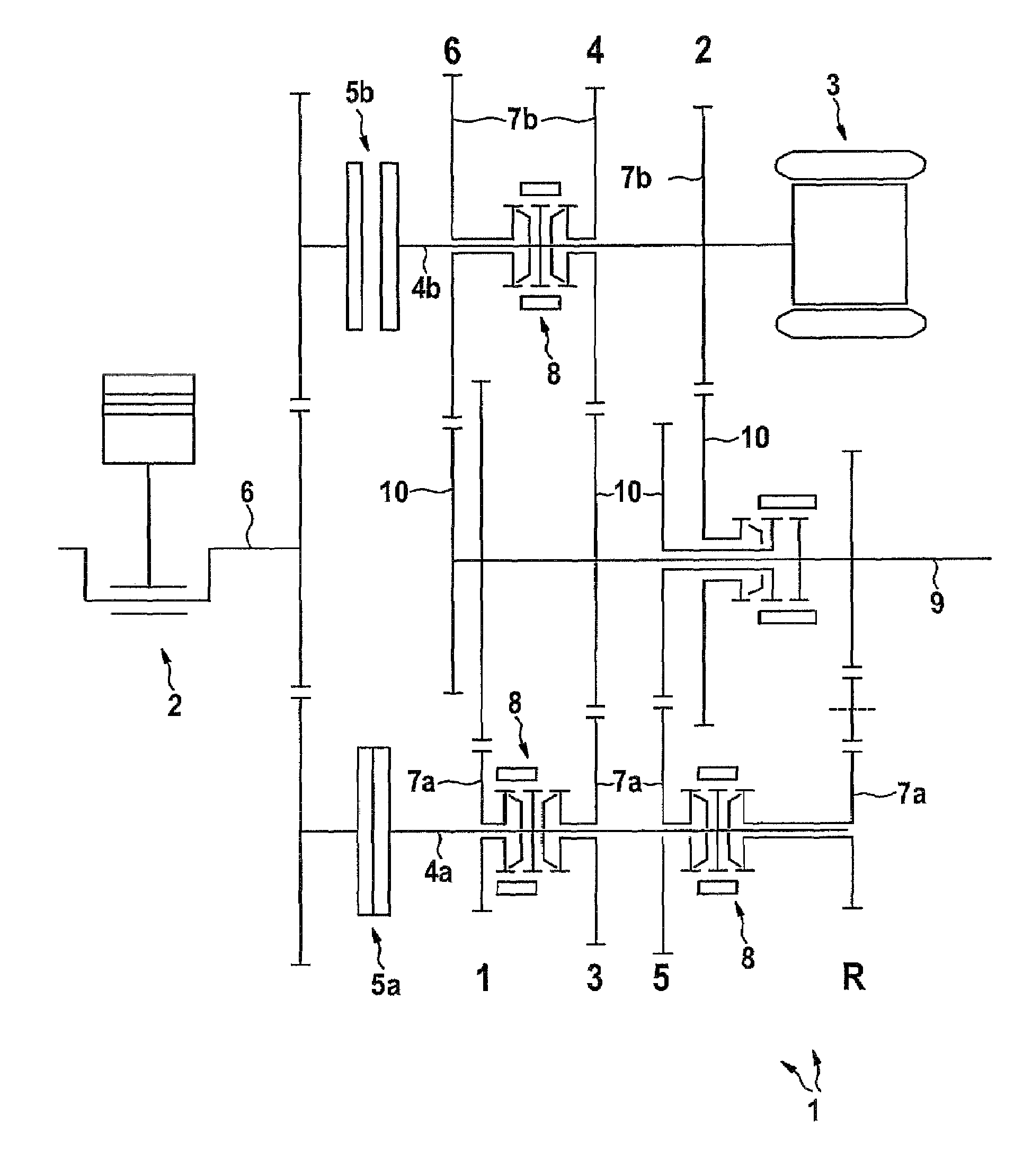
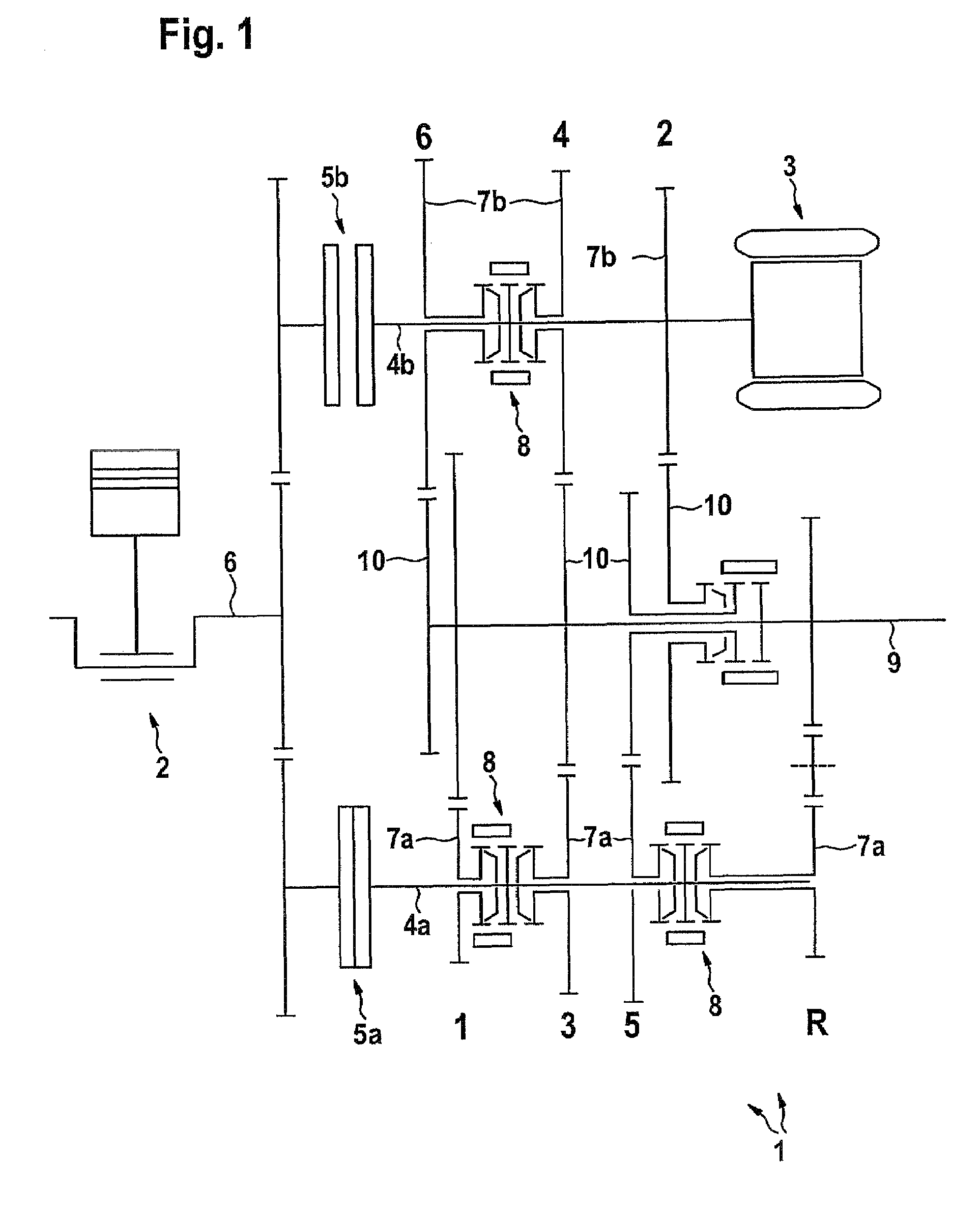
[0034]A hybrid drive train designated as 1 in FIG. 1 for a motor vehicle comprises an internal combustion engine 2 and an electric motor 3 as drive units, which are connected to the drive wheels of the motor vehicle, which are not shown in detail in the drawing, through a parallel variable speed transmission.

[0035]The parallel variable speed transmission comprises a first transmission input shaft 4a, which can be connected through a first clutch 5a with a drive shaft 6, like e.g. the crank shaft of the internal combustion engine 2. A second transmission input shaft 4b of the parallel variable speed transmission can be connected to the drive shaft 6 through a second clutch 5b. The electric motor 3 is furthermore in driving engagement with the second transmission input shaft 4b. The electric motor 3 can be disposed coaxial to the second transmission input shaft 4b, or it can be spaced laterally from it and it can be connected through a chain or through a similar transmission means to ...


PUM


Abstract

The hybrid drive train has an internal combustion engine connected to a first input shaft via a first clutch and connected to a second input shaft via a second clutch. An electric machine is connected to the second input shaft. The first input shaft is coupled to an output shaft via a first gear, and the second input shaft is coupled to the output shaft via two second gears. In the method for operating the hybrid, the first gear is engaged and torque is applied by the engine. To change, one of the second gears is engaged, engine torque is reduced by slipping the clutch while electric machine torque is increased. To change again, electric machine torque is reduced to zero, the other second gear is engaged while engine torque transmitted via the first clutch is increased by reducing slipping of the first clutch.

Description

[0001]This application is a continuation application of PCT / DE2007 / 001475 filed Aug. 20, 2007, which in turn claims the priority of DE 10 2006 043 329.7 filed Sep. 15, 2006, the priority of both applications is hereby claimed and both applications are incorporated by reference herein.BACKGROUND OF THE INVENTION[0002]The invention relates to a method for operating a hybrid drive train for a motor vehicle, wherein the hybrid drive train comprises an internal combustion engine and an electric motor as drive units, and wherein a parallel variable speed transmission with a first transmission input shaft, a second transmission input shaft and a transmission output shaft is disposed in the hybrid drive train, wherein the first transmission input shaft can be coupled to the transmission output shaft through at least a first gear and the second transmission input shaft can be coupled to the transmission output shaft by at least a second gear, wherein the internal combustion engine can be bro...

Claims


Application Information

Patent Timeline
Patent Type & Authority Patents(United States)
IPC IPC(8): B60W10/08B60W10/02H02P15/00B60W10/04B60W10/10
CPCB60K6/40B60K6/547B60W10/02B60W10/08B60W10/113F16H3/006F16H61/0437F16H61/688B60K6/48Y10T477/27B60W20/00B60W2510/0695B60Y2400/428F16H63/502F16H2061/0425F16H2061/0429F16H2200/0052Y02T10/6221Y10S903/946Y10T477/32Y10T477/26Y10T74/19233Y02T10/62B60W2510/02B60W2050/004
Inventor DILZER, MARTIN
Owner SCHAEFFLER TECH AG & CO KG
Learn More