
Electrical switch

a switch and electric technology, applied in circuit-breaking switches, magnetic bodies, contact mechanisms, etc., can solve the problems of high power consumption, achieve the effect of saving energy, being more reliable, and being more practical

Inactive Publication Date: 2009-11-24
LIU PING
View PDF20 Cites 30 Cited by
  • Summary
  • Abstract
  • Description
  • Claims
  • Application Information

AI Technical Summary

Benefits of technology

"The present invention provides an electrical switch that can connect, break, and protect the circuit. The switch has a compact size and can save energy. It includes a connecting and breaking mechanism, an electromagnetism drive mechanism, a housing, an arc-extinguishing mechanism, a case, a bedplate, and a holding mechanism. The switch can detect and limit over-current, and can be used in a selective or non-selective type. The switch is easy to operate and can be used to connect and disconnect the circuit."

Problems solved by technology

The present inventor disassembled and analyzed the product manufactured by TE Company, and found out that it was too complicated to describe, at the same time, the product always keeps in the closed state as a contactor, and the power consumption is high.

Method used


Image

  • Electrical switch
  • Electrical switch
  • Electrical switch

Examples


Embodiment Construction

[0093]The electrical switch according to the present invention will hereinafter be described in details by reference to the attached drawings.

[0094]1. The Electrical Circuit of the Electrical Switch

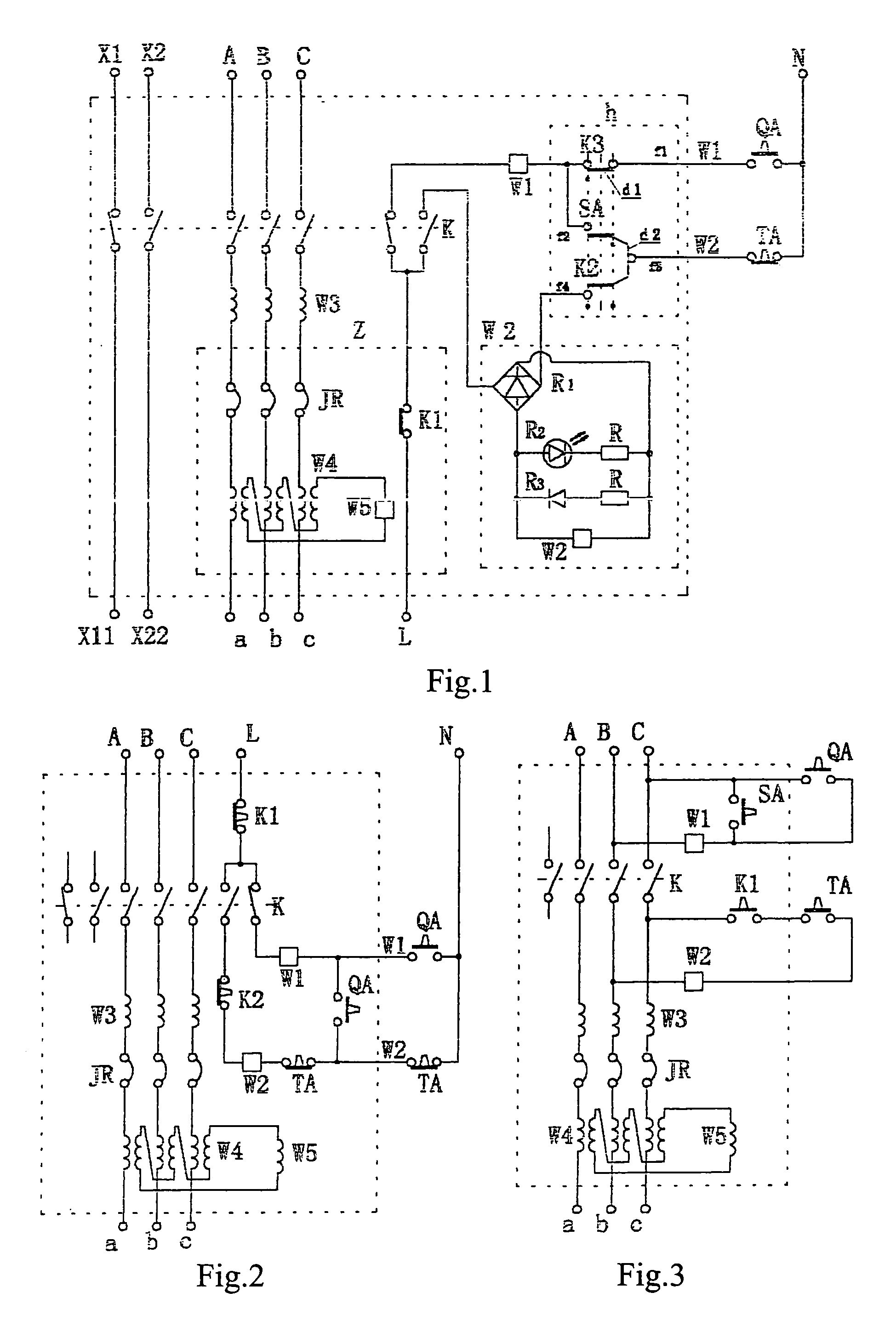
[0095]FIG. 1 is a circuit diagram shows one of the features of the present invention, in which after the switch is attracted and closed by means of the contact inside the switch, the circuit can assure the attracting coil to be powered off immediately, while can keep the holding coil be powered on so as to be on a self-protected state, if the switch is selected to be operated by the remote button, it can reduce one self-protection wire compared with the contactor, therefore, it is simple.

[0096]FIG. 1 shows one preferred circuit of the selective electrical switch, in which the elements and the circuit in the switch are disposed in the large broken line block, A, B, C are input source terminals respectively, a, b, c are input load terminals respectively, x1, x11, x2, x22 are output assistan...


PUM


Abstract

An electrical switch for connecting and breaking a circuit including a connecting and breaking mechanism for connecting and breaking the circuit provided with at least a set of movable contacts and stationary contacts; a electromagnetism drive mechanism for controlling the contacts to be actuated so as to realize closed circuit; a housing for accommodating the movable contact and stationary contact; an arc-extinguishing mechanism disposed in the housing and corresponded to the movable and stationary contact; a case connected to a base for accommodating the electromagnetism drive mechanism; a bedplate associated with the case; and a holding mechanism disposed on the bedplate for holding the contacts to connect the circuit, the electromagnetic holding mechanism is electromagnetic and has a set of electromagnetic attracting mechanism in which the movable iron core is made to be a pothook or a baffle mechanism, the movable iron core is attracted so that the pothook or baffle keeps the switch closed by means of hitching or ramming the movable bolt when the electromagnetic attracting mechanism is powered on. The electrical switch has a structure in which it has a breakaway mechanism using winding, in which the remanence being small and the feedback force being large and the action of the limiting current being rapid, it can break the large short current as air switch.

Description

[0001]This application claims the benefit of PCT Application No. PCT / CN2004 / 000563 filed May 28, 2004 which further claims the benefit of Chinese Patent Application No. 03140553.3 filed May 29, 2003. The entire disclosures of PCT Application No. PCT / CN2004 / 000563 and Chinese Patent Application No. 03140553.3 (Publication No. 1553464A) are incorporated by reference as part of the specification of this application.FIELD OF THE INVENTION[0002]The present invention relates to an apparatus for connecting and breaking a circuit between a load and a power supply, which can be called an electrical switch and may be one single phase or three-phase switch. The present invention mainly introduces one three-phase electrical switch, whose load is a three-phase AC motor.DESCRIPTION OF THE RELATED ART[0003]In 1983, an Integral 32 combination electrical appliance was put on the market by Telemecanique (TE) Company in France, it represents the world's level today, FIG. 45 is view showing the structu...

Claims


Application Information

Patent Timeline
Patent Type & Authority Patents(United States)
IPC IPC(8): H01H75/00H01H77/00H01H83/00H01H71/00
CPCH01H50/32H01H89/08H01H50/60H01H71/2436H01H50/546
Inventor LIU, PING
Owner LIU PING
Learn More