
Device and system for emergency vehicle lighting

a technology for emergency vehicles and devices, applied in the field of emergency vehicle lighting, can solve problems such as obstructing the view of vehicles approaching at acute angles, disadvantaged vehicles approaching emergency vehicles at right angles (broadside), and achieve the effect of enhancing the visibility of emergency vehicles

Inactive Publication Date: 2009-11-24
ADVANCED FITNESS SOLUTIONS
View PDF8 Cites 38 Cited by
  • Summary
  • Abstract
  • Description
  • Claims
  • Application Information

AI Technical Summary

Benefits of technology

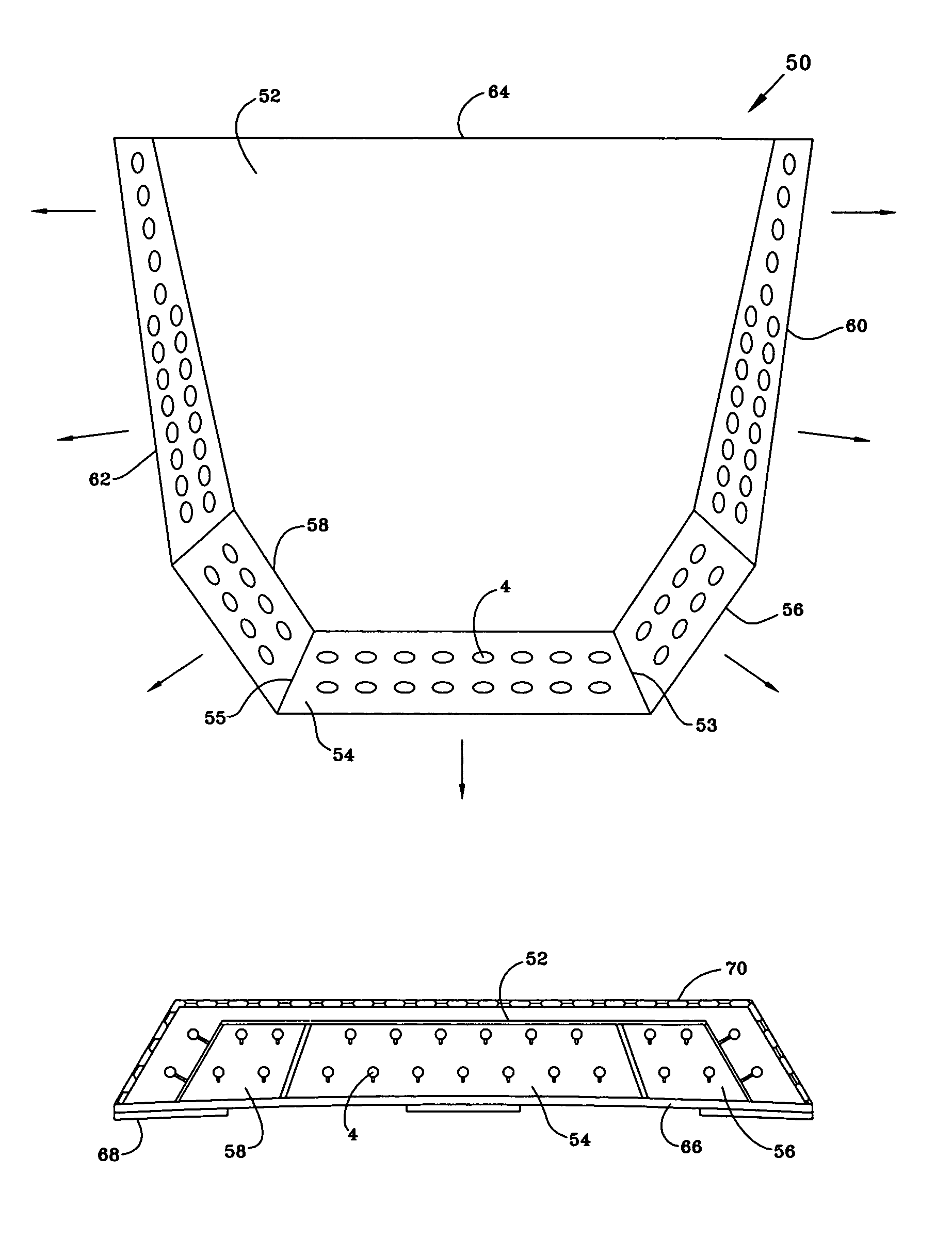
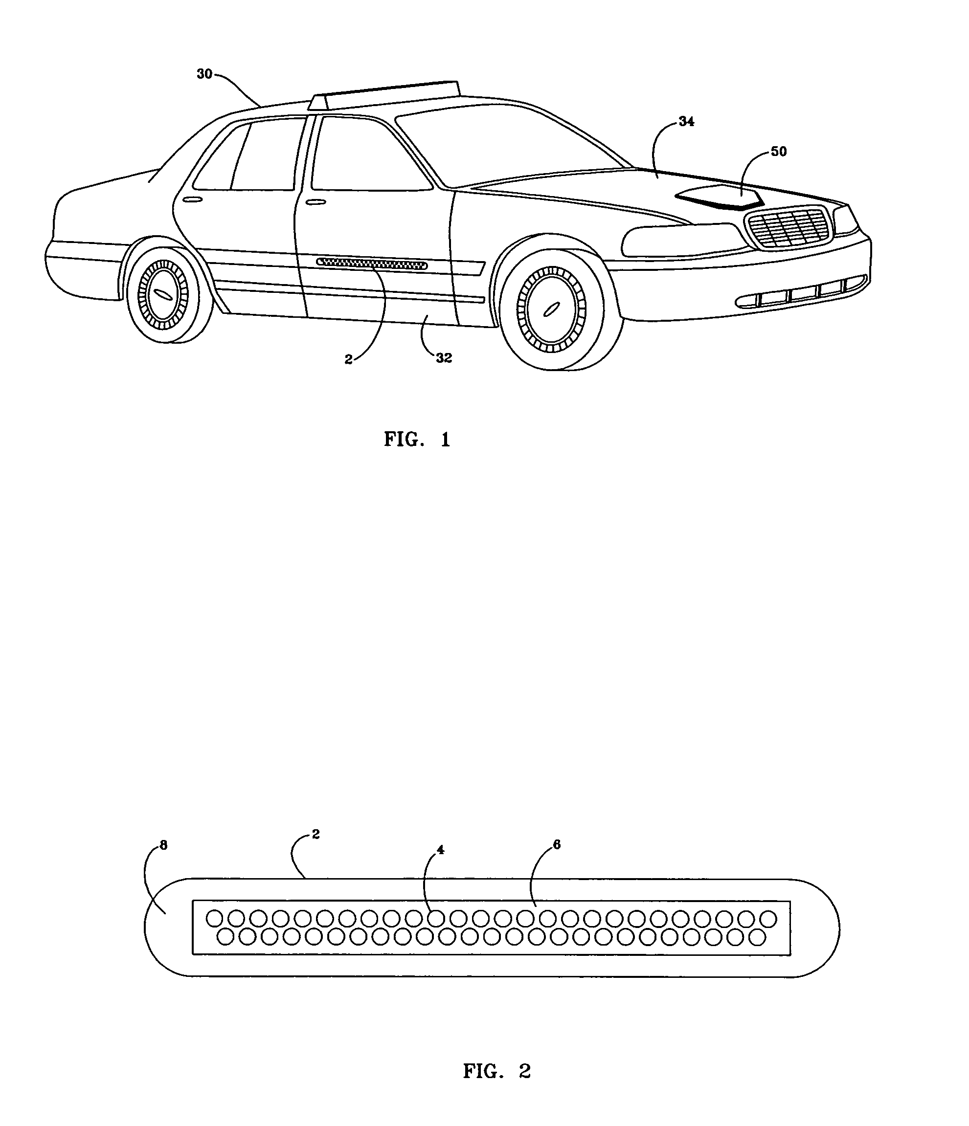
[0007]The general purpose of the present invention, which will be described subsequently in greater detail, is to provide a lighting system for an emergency vehicle that is able to enhance the visibility of the emergency vehicle especially to those people in vehicles approaching the emergency vehicle at right angles.
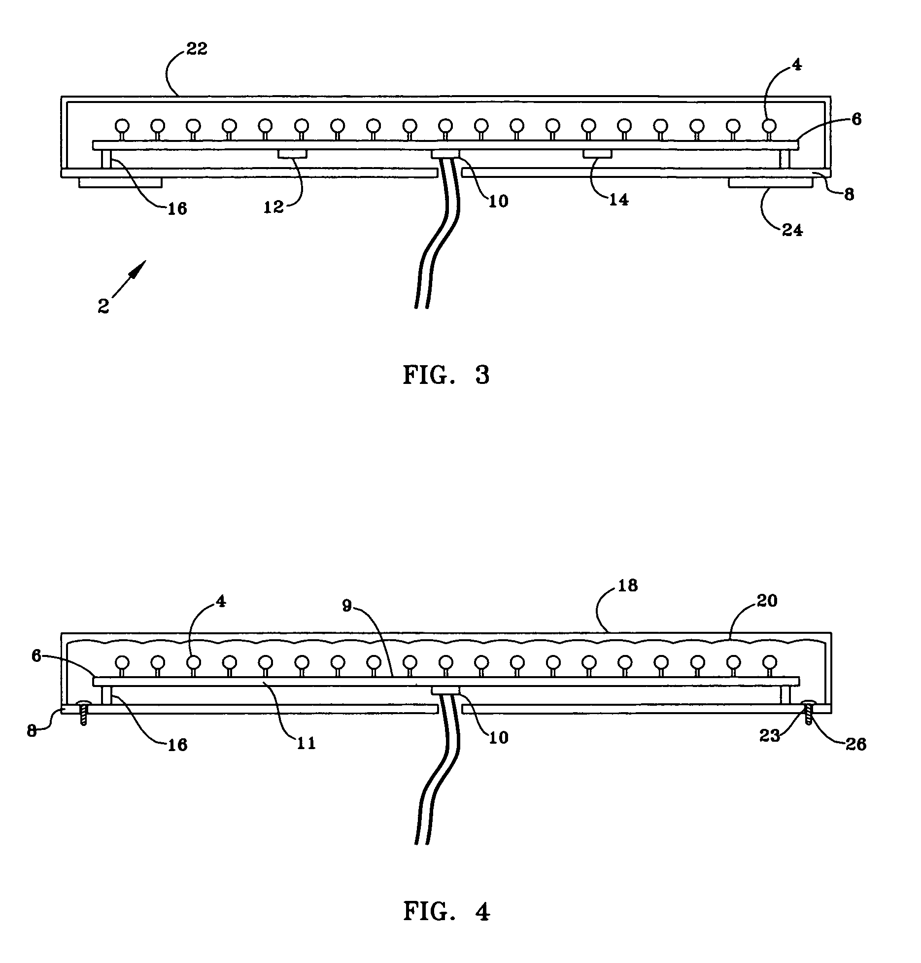
[0009]In accordance with the invention, an object of the present invention is to provide an improved vehicular external lighting system capable of operating with a low current draw and able to be simply integrated into an existing vehicle's electrical system or electronic alarm sequencer system.
[0010]It is another object of this invention to provide an improved emergency vehicle external lighting system capable of providing enhanced visual notification to drivers of vehicles approaching the emergency vehicle normally with respect to either side of the longitudinal centerline of the emergency vehicle.
[0011]It is a further object of this invention to provide a low cost, light weight, vehicular external lighting system that can be temporarily or permanently mounted on a vehicle and is not subject to mechanical failure that will affect the multi directional visibility.
[0012]It is still a further object of this invention to provide for a low profile, high visibility light emitting visual notification system that when not in use has a barely perceptible configuration as affixed to a vehicle.
[0013]It is yet a further object of this invention to provide an enhanced vehicular alert lighting system that has a three dimensional geometrical configuration that allows the light emitted to be seen from an approximate 135 degree horizontal viewing angle from either side of the longitudinal centerline of the emergency vehicle, and to be seen in vertical field of view that encompasses all possible situations.

Problems solved by technology

While in most situations any of the aforementioned devices will adequately alert a passerby of the presence of the emergency vehicle, there are crucial situations in which this is not the case.
Specifically, when an emergency vehicle must enter into an intersection at the junction of more than one road, problems arise.
When exigent circumstances exist, the emergency vehicle often has to traverse the intersection against the prevailing traffic light.
While those vehicles approaching approximately head on with the emergency vehicle receive the benefit of all of the emergency vehicle's alert devices, objects such as trees, bushes, other vehicles, or knolls often obstruct the view that vehicles approaching at acute angles have.
Additionally, vehicles approaching the emergency vehicle at right angles (broadside) are already disadvantaged because they do not have the benefit of a visual line of sight with the emergency vehicle's front flashing lights as well as much of the roof mounted light bar alerts.
A similar problem arises when the emergency vehicle must be left unattended in an intersection, as is often the case at intersection accidents or where access to a road must be physically blocked from use by the emergency vehicle.
Vehicles approaching the emergency vehicle at right angles are at the greatest danger of colliding with the emergency vehicle.

Method used


Image

  • Device and system for emergency vehicle lighting
  • Device and system for emergency vehicle lighting
  • Device and system for emergency vehicle lighting

Examples


Embodiment Construction

[0028]There has thus been outlined, rather broadly, the more important features of the invention in order that the detailed description thereof that follows may be better understood and in order that the present contribution to the art may be better appreciated. There are, of course, additional features of the invention that will be described hereinafter and which will form the subject matter of the claims appended hereto.

[0029]In this respect, before explaining at least one embodiment of the invention in detail, it is to be understood that the invention is not limited in its application to the details of construction and to the arrangements of the components set forth in the following description or illustrated in the drawings. The invention is capable of other embodiments and of being practiced and carried out in various ways. Also, it is to be understood that the phraseology and terminology employed herein are for the purpose of descriptions and should not be regarded as limiting...


PUM


Abstract

The present invention is a system of emergency vehicle lighting that uses a low profile hood / trunk mounted LED plate unit and a door mounted LED strip unit. It is designed for both stand alone operation or for integration into an emergency vehicle's electronic alarm notification sequencing unit. The hood / trunk LED plate unit has a thin, enhanced geometrical configuration and an LED lens design that allows the light emitted from the superbright LEDs to be seen to a much higher degree to vehicles approaching from direction normal to the longitudinal centerline of the emergency vehicle. Mounting of the LED plate unit and LED strip unit can be permanent or temporary and because of the light weight, numerous chemical, magnetic and mechanical methods of affixation may be utilized.

Description

BACKGROUND OF THE INVENTION[0001]The present invention relates to a lighting system that can be removably affixed to an emergency vehicle to enhance the visibility of the emergency vehicle from all angles and from a distance that allows ample time for corrective action on the part of approaching drivers. More particularly, to a inexpensive exterior lighting system that can be easily integrated into the vehicle's electrical system or electronic alert sequencing unit and attached to exterior locations about the emergency vehicle such as the door or hood.[0002]Most conventional emergency vehicles today have a variable audible alert, sequenced flashing head / tail / side light assemblies and a roof mounted light bar containing at least one light source designed to disburse light in 360 degrees. These lights may be solid, stroboscopic, revolving, flashing, modulated, pulsing, oscillating, alternating or any combination thereof. While in most situations any of the aforementioned devices will ...

Claims


Application Information

Patent Timeline
IPC IPC(8): B60Q1/26
CPCB60Q1/2611B60Q1/52B60Q1/46B60Q1/2615
Inventor COLBERT, TERRY THOMAS
Owner ADVANCED FITNESS SOLUTIONS
Learn More