Stackable casting sinker

a sinker and elongated bar technology, applied in the field of sinkers, can solve the problems of reducing the likelihood of the lashing slipping off the elongated bars, and achieve the effects of reducing the likelihood of snagging

Inactive Publication Date: 2009-11-24
BRASSEUR BERNARD P
View PDF206 Cites 14 Cited by
  • Summary
  • Abstract
  • Description
  • Claims
  • Application Information

AI Technical Summary

Benefits of technology

[0010]The present invention provides a stackable weight designed to be used as a building element for an adjustable-weight modular sinker, as well as the resulting sinker, which is particularly well suited for casting. The stackable weight is configured to be bundled with additional, similar stackable weights and bound together with a lashing to form a composite sinker of the desired weight, the resulting sinker being compact and attaching to the fishing line in such a manner as to reduce the likelihood of becoming snagged.
[0011]Each stackable weight has an elongated bar terminating in a leading end and a trailing end, and bounded by four side surfaces which provide a rectangular cross section. Each of the stackable weights has a fixed eye attached to the leading end of the elongated bar. A link member movably attaches to the fixed eye and terminates in a coupling eye, the movable attachment of the link member to the fixed eye serving to provide a degree of motion between the coupling eye the elongated bar. This motion allows the coupling eyes to be connected together to a single fastener when the elongated bars are stacked in a side-by-side relationship with their leading ends positioned together. When the coupling eyes are connected together in this manner, the link members form triangular-shaped coupling units that, when connected together, form a pyramid-like structure that will reduce the likelihood of snagging by providing flexible ramp surfaces that can ride over blocking obstructions such as rocks and weed tangles that could otherwise catch on the leading ends of the elongated bars. Preferably, the leading ends of the elongated bars are tapered to further reduce the likelihood of snagging.
[0012]A lashing, such as an elastic band, is provided to complete the sinker. The lashing binds the stacked weights, thus forming a bundle of the stackable weights positioned in a side-by-side relationship, with their link members arranged to be connected to a single, common fastener. This bundle of weights forms the resulting sinker, wherein the stackable weights can be readily added or removed without requiring special tools while still maintaining a compact sinker well suited for casting. Connecting the link members to a single fastener not only provides a snag-resistant structure, as pointed out above, but also provides connectivity of the weights in service even in the event that the lashing breaks.
[0013]The side surfaces of the elongated bars are preferably textured to increase sliding resistance between side surfaces of adjacent elongated bars, and between the elongated bars and the lashing without requiring special connecting elements that may complicate assemby of the desired weight size in the field while fishing. The increased friction between the side surfaces of adjacent elongated bars helps maintain the elongated bars aligned, and allows the use of a single elastic band for the lashing. The friction between the side surfaces and the lashing reduces the likelihood of the lashing slipping off the elongated bars due to rubbing against rocks or other submerged objects. The textured surfaces, in combination with the substantially rectangular cross section, may also help the stackable weights to stay in place on the water bottom to maintain the lure or bait at a desired location until deliberately moved by tension applied to the line by the angler. Such textured side surfaces can be provided by scoring, stamping, or pressing the side surfaces. When the elongated bars are formed of lead, pressing a texture pattern having strong diagonal elements into the side surfaces has been found to provide increased stiffness for the elongated bars.

Problems solved by technology

The friction between the side surfaces and the lashing reduces the likelihood of the lashing slipping off the elongated bars due to rubbing against rocks or other submerged objects.

Method used


Image

  • Stackable casting sinker
  • Stackable casting sinker
  • Stackable casting sinker

Examples


Embodiment Construction

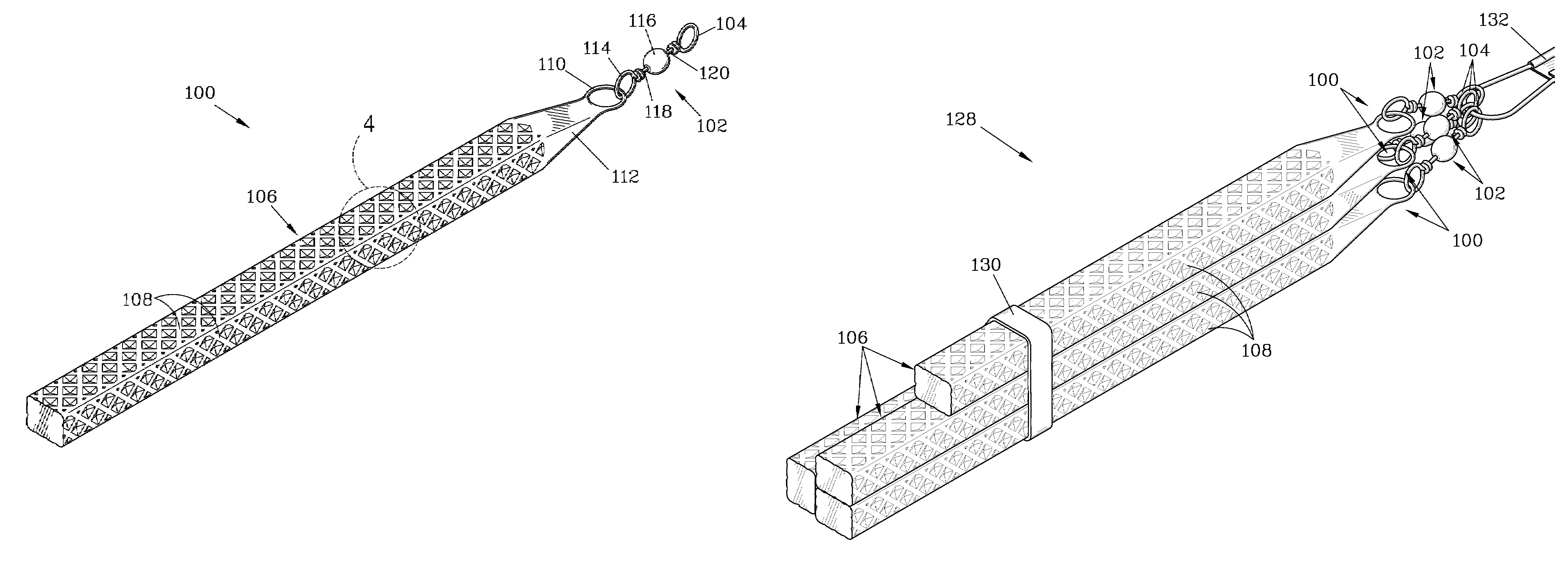
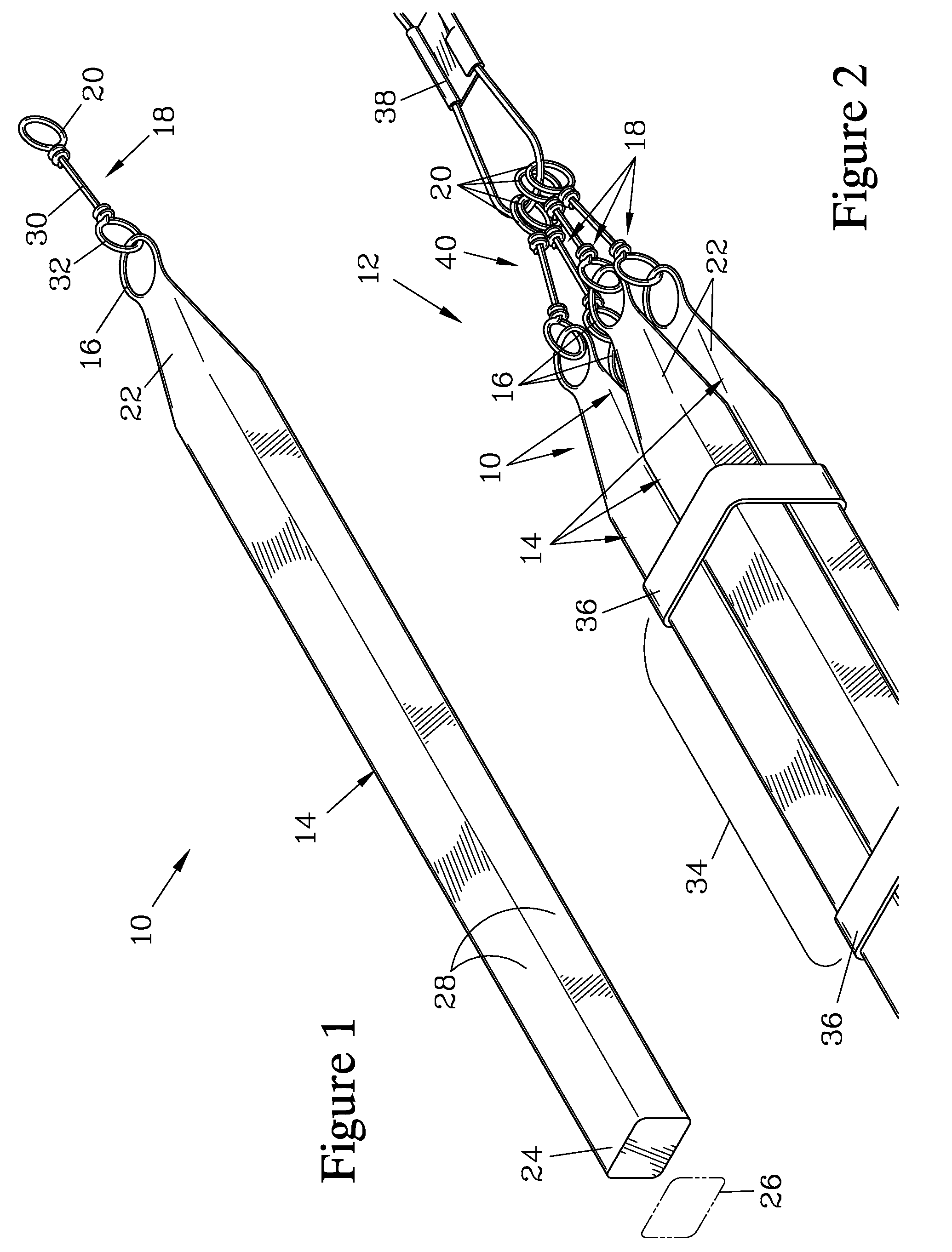
[0020]FIG. 1 is an isometric view of a stackable weight 10 which can be bundled with similar stackable weights 10 to form a modular sinker 12 of the desired weight, as shown in FIG. 2. The stackable weight 10 has an elongated bar 14 with a fixed eye 16 attached thereto, and a link member 18. The link member 18 has a coupling eye 20, and is movably attached to the fixed eye 16.

[0021]The elongated bar 14 terminates in a leading end 22, to which the fixed eye 16 attaches, and a trailing end 24. Preferably, the fixed eye 16 is embedded in or forms an integral part of the leading end 22. The elongated bar 14 has a rectangular cross section 26 formed by four substantially planar side surfaces 28. The trailing end 24 is a substantially flat planar surface that is normal to the four substantially planar side surfaces 28. The elongated bar 14 should be formed from a dense, durable material, and typically will be made of metal. Examples of preferred metals are lead, tin, and alloys thereof.

[0...


PUM


Abstract

A number of stackable weights can be bundled together and secured with a lashing to form a modular sinker of a desired weight. Each stackable weight has an elongated bar bounded by four side surfaces and having a fixed eye. A link member is movably attached to the fixed eye and terminates in a coupling eye. The link member provides a degree of motion between the coupling eye and the fixed eye of the bar, allowing the coupling eyes of multiple stackable weights to be connected together to a single fastener while the bars are positioned together in a side-by-side relationship. When so connected, the link members form a pyramid-shaped coupling structure that will reduce the likelihood of snagging the resulting modular sinker. The bars preferably have textured side surfaces to frictionally engage each other to maintain the bars parallel and to retain an elastic band that provides the lashing.

Description

FIELD OF THE INVENTION[0001]The present invention relates to sinkers employed to hold a fishing line near the bottom of a body of water, and more particularly to a modular sinker which allows the user to readily form a sinker of the desired weight while reducing the tendency of the sinker to snag or become entangled by obstructions or weeds.BACKGROUND OF THE INVENTION[0002]Anglers frequently use a rod to cast a lure or bait attached to a line in order to place the lure or bait at a desired location in the water where the angler hopes to find fish. Typically, one or more sinkers are attached to the line. The sinker serves to provide sufficient weight on the line to flex the rod during the casting action, and provides weight to carry the line against the resistance of air to the desired location. The sinker then serves to maintain the lure or bait in close proximity to the bottom of a body of water.[0003]Unfortunately, sinkers are prone to snagging on weeds, rocks, submerged branches,...

Claims


Application Information

Patent Timeline
Patent Type & Authority Patents(United States)
IPC IPC(8): A01K95/00
CPCA01K95/00A01K91/08
Inventor BRASSEUR, BERNARD P.
Owner BRASSEUR BERNARD P
Why Eureka
Try Eureka