
Seawall filter

a filter and seawall technology, applied in the field of seawalls, can solve the problems of difficult to drive the conduit into the hole, excessive soil escape, and damage to the seawall, and achieve the effects of convenient installation, convenient service, and greater surface area of filtration

Active Publication Date: 2009-11-10
JET FILTER SYST
View PDF13 Cites 18 Cited by
  • Summary
  • Abstract
  • Description
  • Claims
  • Application Information

AI Technical Summary

Benefits of technology

[0009]The general object of this invention is to provide an improved seawall filter assembly. More particular objects are to provide a seawall filter assembly that is easier to install, easier to service, has a much greater surface area of filtration, and is flush with the outer surface of the seawall.
[0011]The seawall filter assembly of this invention is easy to install because the hole in the seawall is sealed by the flange of the housing so that the shell of the housing need not fit tightly into the hole. The seawall filter assembly is easy to service because no tools are required to gain access to the filter element from the seaward side of the seawall. The seawall filter has a much greater surface area of filtration because its filter element is a cone rather than a disc. The flange of the housing and the cap fit flushly against the outer surface of the seawall so they will not damage boats and so that they are less likely to be damaged themselves.

Problems solved by technology

Without a mechanism for relieving the hydraulic pressure, the seawall can be damaged.
A simple hole in the seawall provides some drainage for water, but also allows excessive amounts of soil to escape.
First, it is difficult to drive the conduit into the hole.
And fourth, the conduit extending outwardly from the seawall can damage boats that dock along the seawall and is, itself, prone to damage.

Method used


Image

  • Seawall filter
  • Seawall filter
  • Seawall filter

Examples


Embodiment Construction

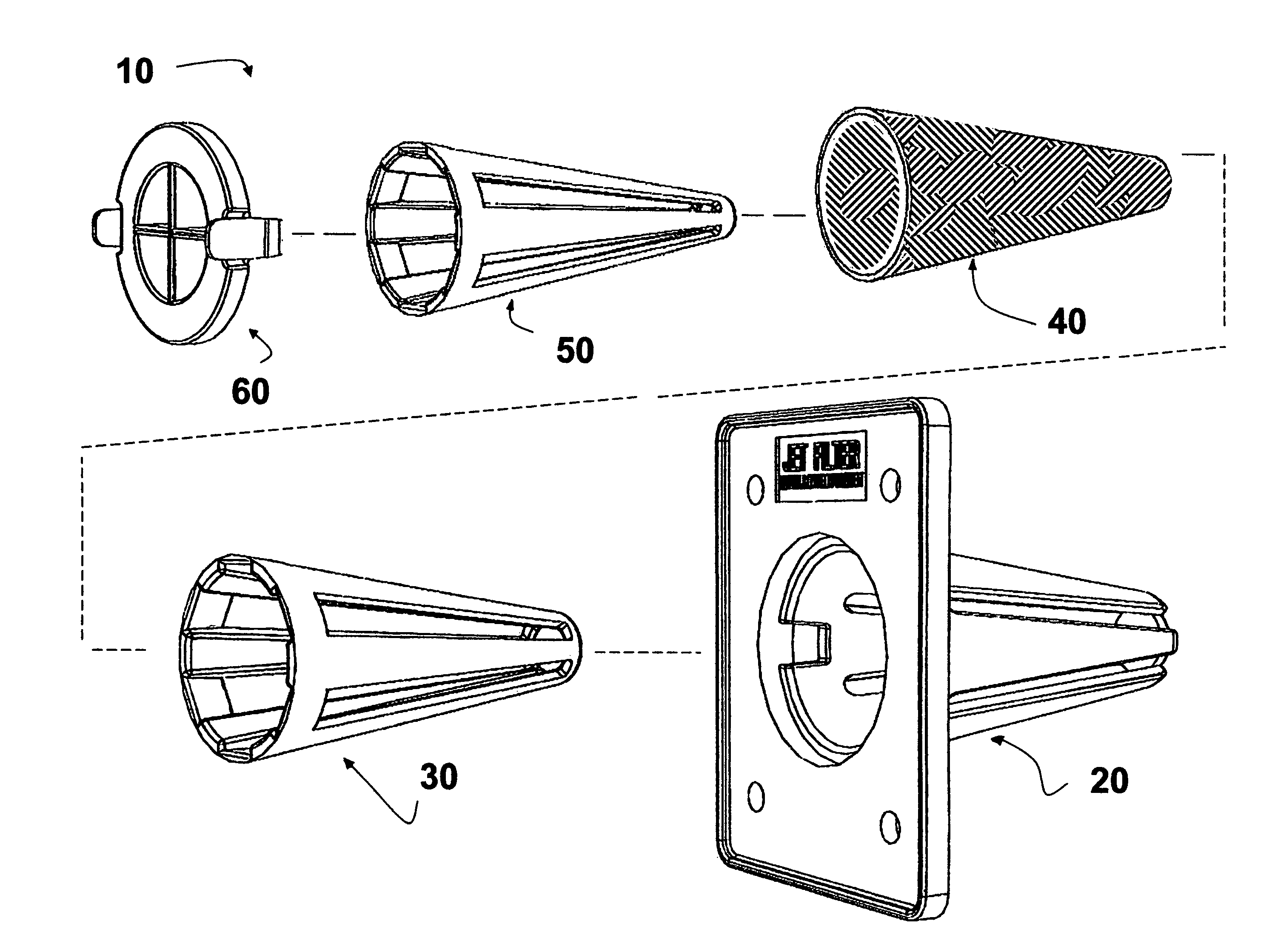
[0028]This invention is best understood by reference to the drawings. Referring first to FIG. 1, the seawall filter assembly 10 of this invention comprises a housing 20, a cage 30, a filter element 40, a sleeve 50, and a cap 60. The housing, cage, filter element, and sleeve are nested, i.e., each one fits within the immediately larger component. They are also conical in shape, i.e., they have a circular cross-section and taper inwardly from a base toward an apex. The shape of the components are described herein using standard geometry terms that are used to describe right circular cones. Each of the components of the seawall filter assembly is discussed in more detail below.

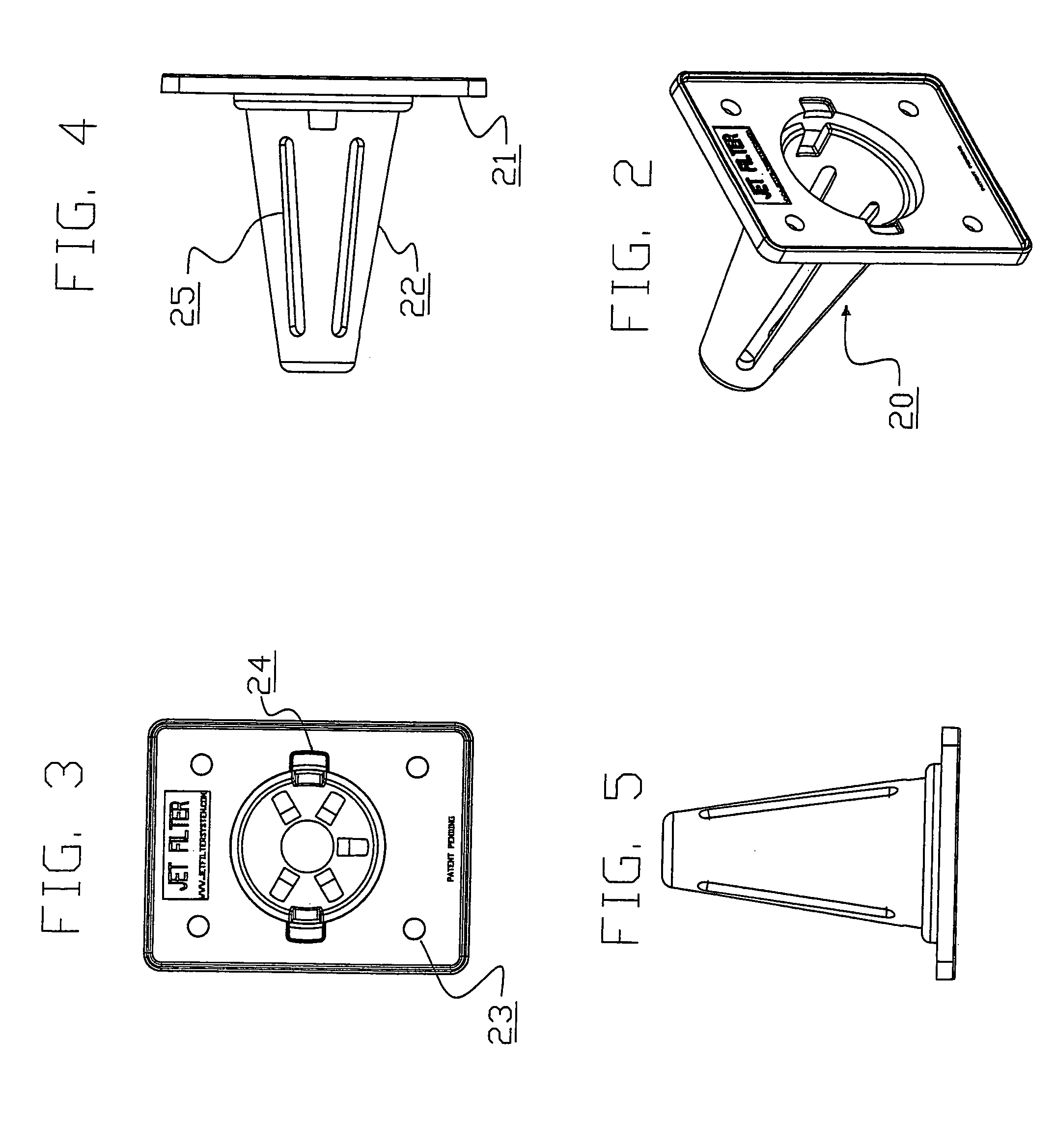
[0029]A preferred embodiment of the housing 20 is illustrated in FIGS. 2 to 5. The housing is adapted to be permanently attached at and into a hole in the seawall. The other components of the assembly fit into the housing. The housing contains a flange 21 and a conical shell 22. The shell is connected to the land...


PUM

PropertyMeasurementUnit
Flow rateaaaaaaaaaa
Surface areaaaaaaaaaaa
Resilienceaaaaaaaaaa

Abstract

A filter assembly for a seawall filters the flow of groundwater through a hole in the wall. The filter assembly includes: (a) a housing containing a flat flange and a perforated conical shell, the shell adapted to extend into the hole with its apex extending toward the landward side, the flange having a seaward side adapted to fit flushly against the seawall, the flange having a landward side connected to the shell, the flange having an opening that defines an open base for the shell; (b) a perforated conical cage having an open base that fits within the shell of the housing; (c) a conical filter element having an open base that fits within the cage; (d) a perforated conical sleeve having an open base that fits within the filter element; and (e) a perforated cap that is removably and flushly fastened to the opening in the flange to secure the cage, filter element, and sleeve within the shell of the housing.

Description

CROSS-REFERENCE TO RELATED APPLICATION[0001]This application claims the benefit of U.S. Provisional Application Ser. No. 60 / 925,003, Apr. 18, 2007.FIELD OF THE INVENTION[0002]This invention relates to hydraulic and earth engineering. More particularly, this invention relates to seawalls.BACKGROUND OF THE INVENTION[0003]Seawalls are commonly built along shorelines to protect the adjoining ground from erosion and to provide an aesthetic appearance to the shoreline. Seawalls typically extend downwardly into the solid bottom of the waterway and extend upwardly a short distance above ground level. Seawalls are made of various materials including poured concrete, masonry blocks, steel or plastic panels, and the like. The term “seawall” is used herein to include retaining walls, bulkheads, sheet pilings and other erosion control barriers between land and water.[0004]When it rains or when waves overlap the seawall, water enters the ground behind the seawall and causes it to expand. The expa...

Claims


Application Information

Patent Timeline
IPC IPC(8): B01D35/02E02B3/04
CPCB01D35/02E03B3/06B01D2201/02
Inventor GENTRY, DAVID W.
Owner JET FILTER SYST
Learn More