
Methods and apparatuses for image processing

a high-dynamic range, imaging technology, applied in the field of high-dynamic range imaging, can solve the problems of poor image quality, poor dynamic range of typical digital cameras, and inability to capture details in a very bright area of the scene, and achieve the effect of low dynamic rang

Active Publication Date: 2009-11-03
APPLE INC
View PDF14 Cites 127 Cited by
  • Summary
  • Abstract
  • Description
  • Claims
  • Application Information

AI Technical Summary

Benefits of technology

[0008]Methods and apparatuses for generating a low dynamic range image for a high dynamic range scene are described here. The low dynamic range image, once generated, can then be displayed or printed on an output device which has a low dynamic range. In one embodiment, the low dyna

Problems solved by technology

For example, a typical digital camera has a limited dynamic range.
With a given exposure setting, the digital camera may not be able to capture the details in a very bright area in the scene, since the bright area in the picture taken by the digital camera is saturated and represented as a nearly uniform white region.
This situation becomes worse when the digital image is coded with 8 bits per channel as in JPEG or TIFF files.
Unfortunately, many existing displays or printers do not provide a high dynamic range output.

Method used


Image

  • Methods and apparatuses for image processing
  • Methods and apparatuses for image processing
  • Methods and apparatuses for image processing

Examples


Embodiment Construction

[0027]The following description and drawings are illustrative of the invention and are not to be construed as limiting the invention. Numerous specific details are described to provide a thorough understanding of the present invention. However, in certain instances, well known or conventional details are not described in order to avoid obscuring the description of the present invention. References to one or an embodiment in the present disclosure are not necessarily references to the same embodiment; and, such references mean at least one.

[0028]In one embodiment of the present invention, details in different ranges and different regions of a high dynamic range scene are blended into a composite image with a lower dynamic range suitable for a low dynamic range device (e.g., a monitor or a printer).

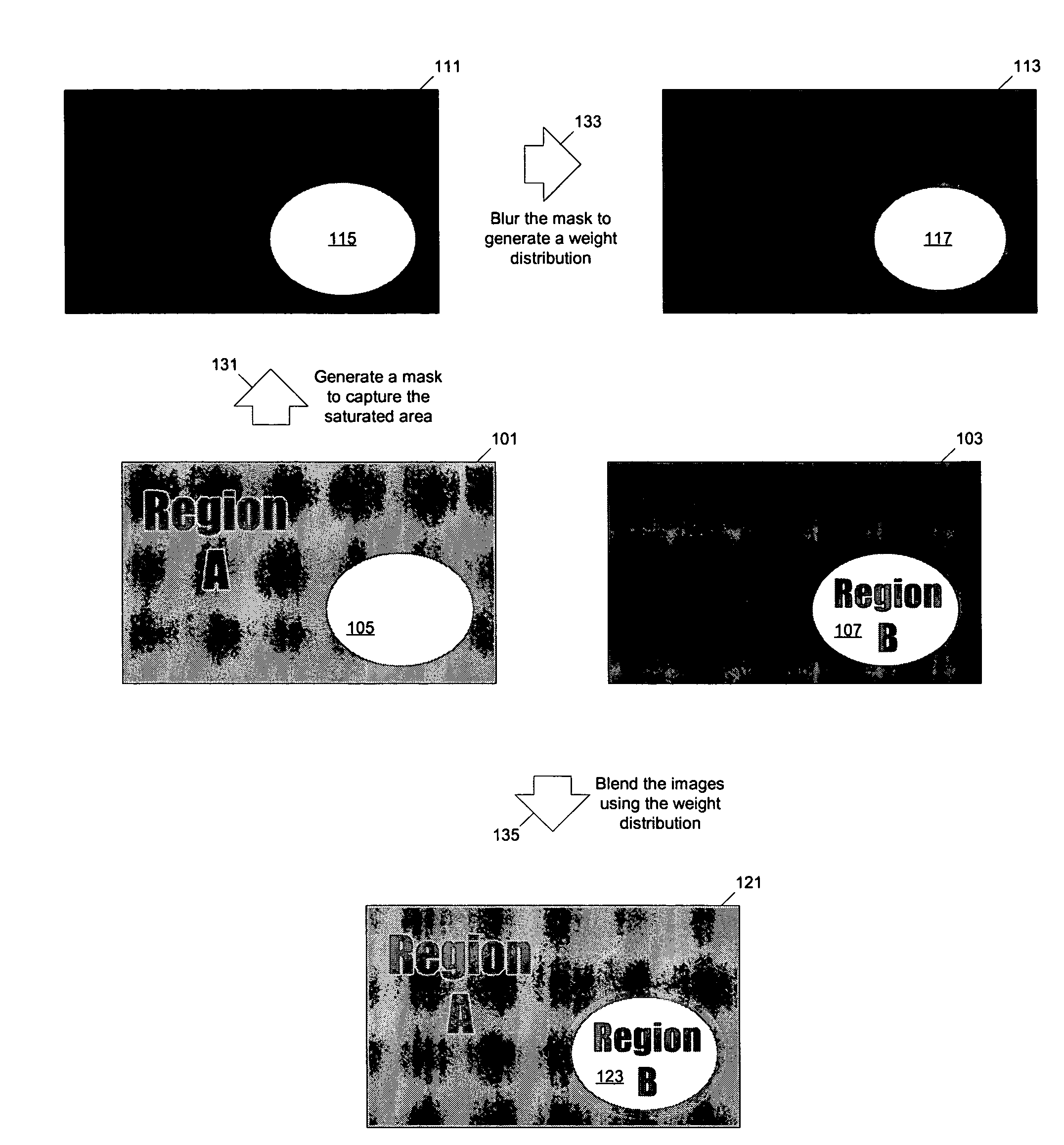
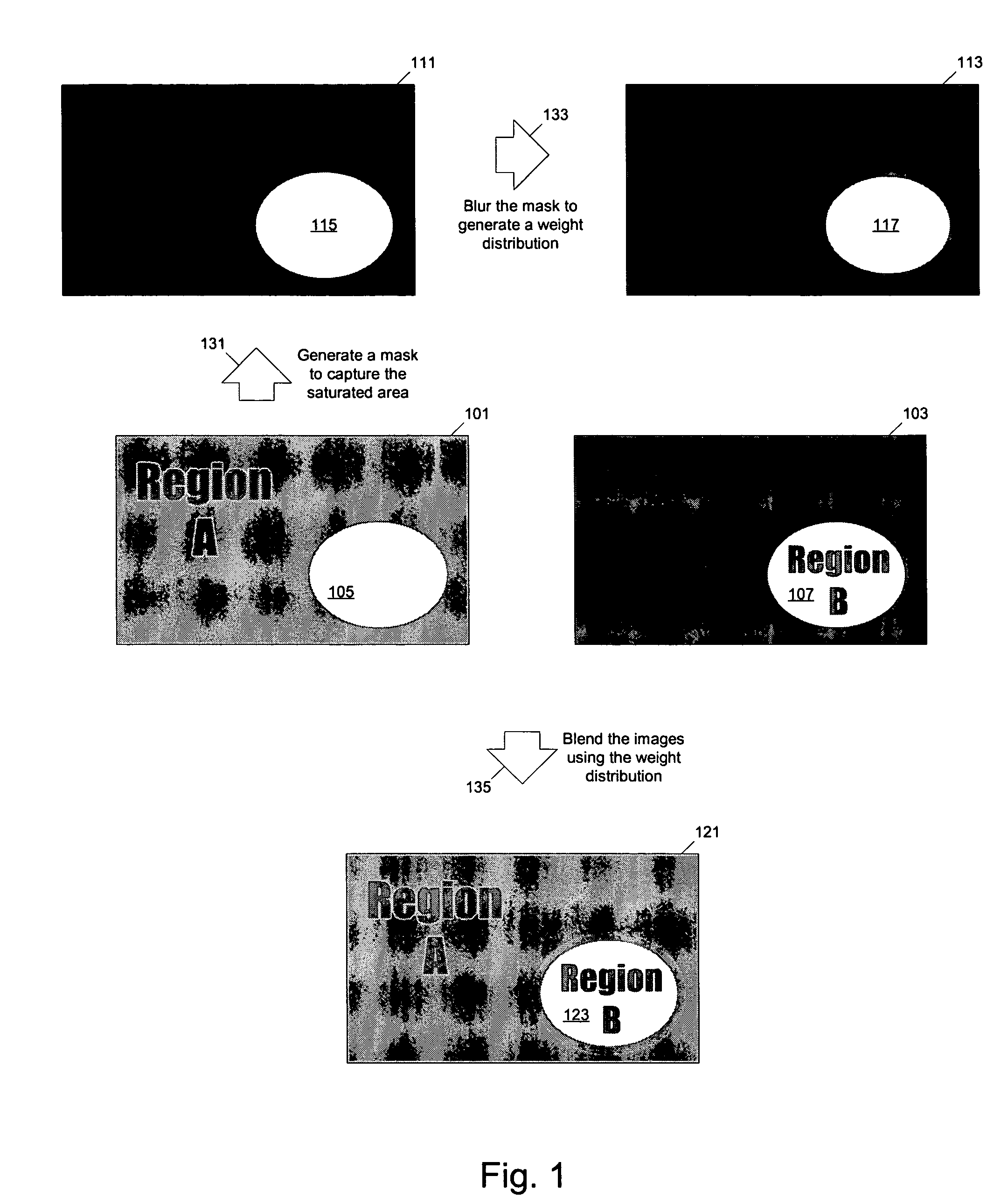
[0029]FIG. 1 illustrates a method to combine low dynamic range images of a high dynamic range scene to generate a low dynamic range image representative of the high dynamic range scene acco...


PUM


Abstract

Methods and apparatuses for generating a low dynamic range image for a high dynamic range scene. In one aspect, a method to generate a low dynamic range image from a high dynamic range image, includes: determining one or more regions of the high dynamic range image containing pixels having values that are outside a first range and inside a second range; computing a weight distribution from the one or more regions; and generating the low dynamic range image from the high dynamic range image using the weight distribution. In another aspect, a method of image processing, includes: detecting one or more regions in a first image of a high dynamic range scene according to a threshold to generate a mask; and blending the first image and a second image of the scene to generate a third image using the mask.

Description

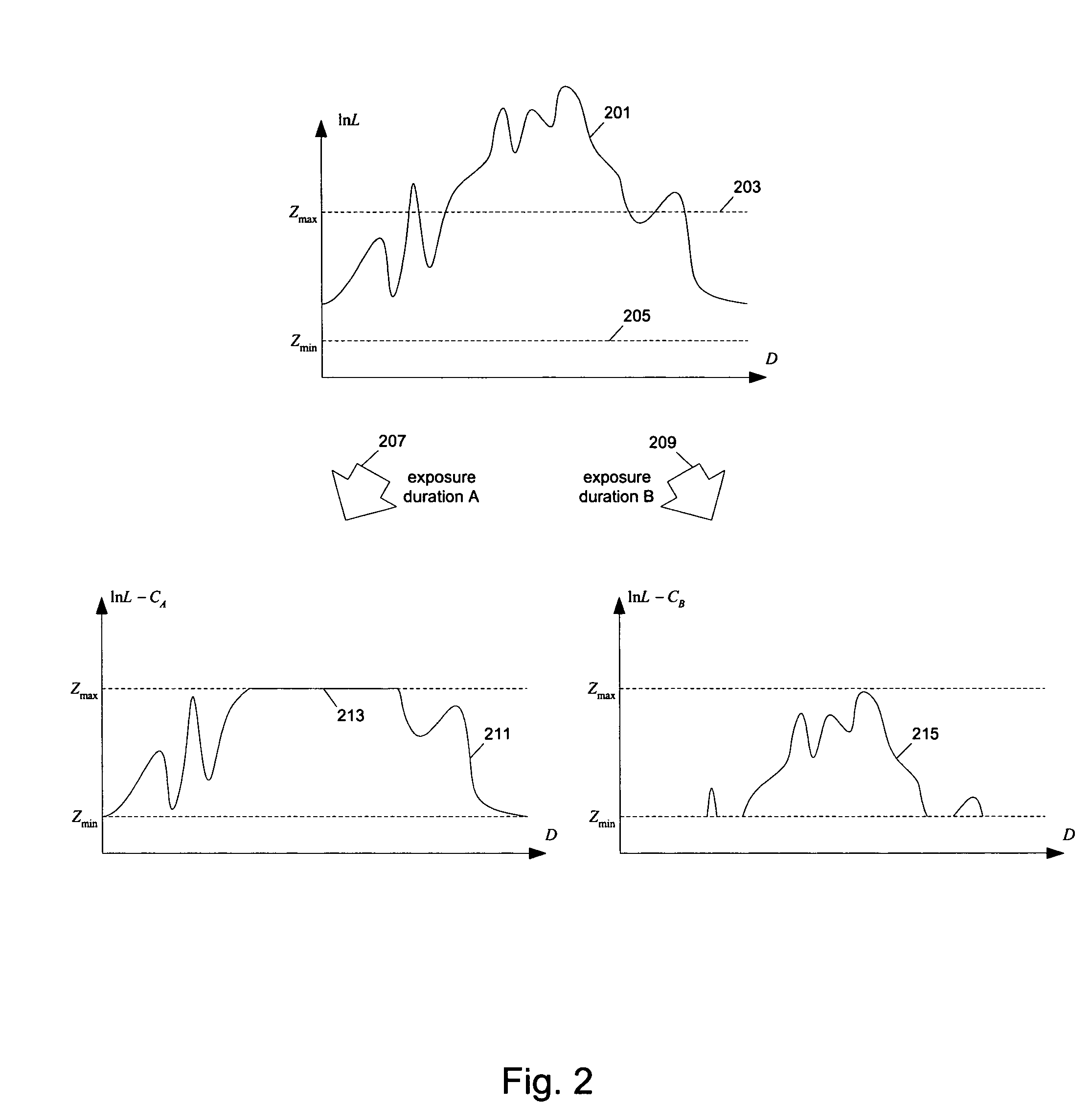
TECHNOLOGY FIELD[0001]At least some embodiments of the present invention relate to high dynamic range imaging, and more particular to presenting high dynamic range scenes in low dynamic range images.BACKGROUND[0002]Dynamic range shows the ratio of a specified maximum level of a parameter to the minimum detectable value of that parameter. High dynamic range imaging allows a greater dynamic range of exposures than normal digital imaging techniques. For example, a high dynamic range image can accurately represent the wide range of intensity levels found in real scenes, ranging from direct sunlight to the dark shadows, which may exceed the ratio of 10000 to 1.[0003]A high dynamic range scene can be captured through a set of differently exposed photographs of the scene. Through changing the exposure duration, details in different portions of the high dynamic range can be captured in the differently exposed photographs.[0004]For example, a typical digital camera has a limited dynamic rang...

Claims


Application Information

Patent Timeline
IPC IPC(8): H04N5/235G06K9/40H04N5/262
CPCG06T5/50H04N5/35581G06T5/007H04N5/2355G06T2207/20012G06T2207/20148G06T2207/20221G06T2207/20208G06T7/136H04N23/741H04N25/589G06T5/90
Inventor MARCU, GABRIEL G.SWEN, STEVE
Owner APPLE INC
Learn More