System and method for conditioning differential clock signals and integrated circuit load board using same

a technology of differential clock signals and load boards, applied in pulse manipulation, pulse techniques, instruments, etc., can solve problems such as propagation delays, limitations and disadvantages, and difficulty in testing various timing characteristics of integrated circuits

Active Publication Date: 2009-11-03
MICRON TECH INC
View PDF2 Cites 20 Cited by
  • Summary
  • Abstract
  • Description
  • Claims
  • Application Information

AI Technical Summary

Problems solved by technology

While the above-described testing environment works well in many applications, it is not without its limitations and disadvantages.
For example, it is very difficult to test various timing characteristics of the integrated circuits, particularly at the high operating speeds for which such integrated circuits are designed.
This difficulty in testing timing characteristics results primarily from the propagation delays in the cable coupling the tester to the test head.
The cables that are typically used in such testing environments are often fairly long, thus making the delays of signals coupled to and from the integrated circuits correspondingly long and often difficult to predict.
Another problem with the above-described testing environment is that it may not accurately simulate the conditions in which the integrated circuits will be actually used.
While techniques have been developed to deal with these difficulties, the use of these techniques results in testers that are highly complex and often very expensive.
A large number of testers are normally required for a high capacity semiconductor fabrication plant, thus greatly increasing the cost of the plant and the expense of testing the integrated circuits.
One difficulty in using an integrated test circuit in this manner stems from the difficulty in generating and / or maintaining high fidelity signals sent to the integrated circuits such as DRAM devices in order to test the devices.
When errors in duty cycle and / or phase placement occur at the inputs of the phase interpolators, the accuracy of clock signals generated by interpolation is affected causing inaccuracies in the testing of the integrated circuits.

Method used


Image

  • System and method for conditioning differential clock signals and integrated circuit load board using same
  • System and method for conditioning differential clock signals and integrated circuit load board using same
  • System and method for conditioning differential clock signals and integrated circuit load board using same

Examples


Embodiment Construction

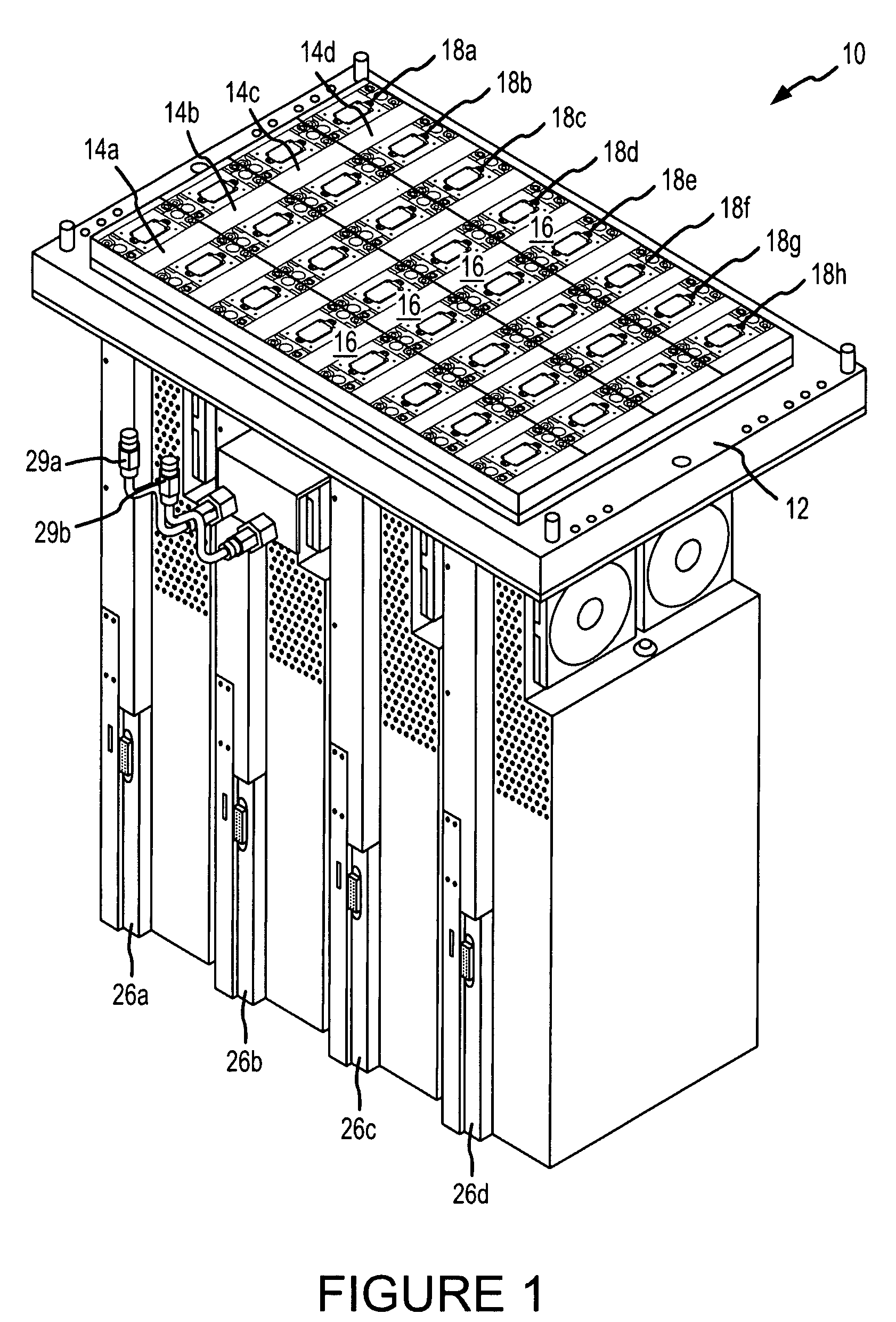
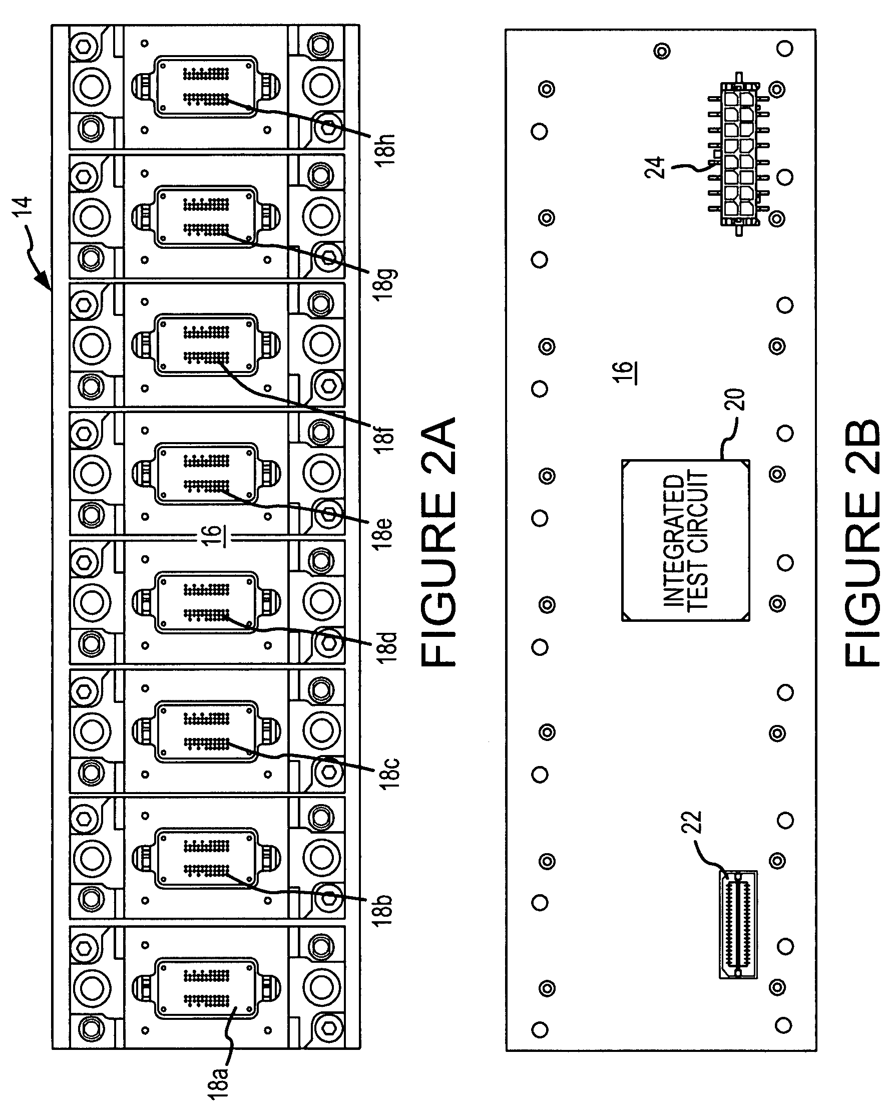
[0015]A test system 10 according to one example of the invention is illustrated in FIG. 1. The test system 10 includes a test head 12 on which several load boards 14a-d are placed. Each of the load boards 14a-d have a printed circuit substrate 16 on which several integrated circuit sockets 18a-h are mounted. Each of the integrated circuit sockets 18a-h receives a respective integrated circuit (not shown in FIG. 1). In the example shown in FIG. 1, the sockets 18a-h are adapted to receive integrated circuit memory devices, such as dynamic random access memory (“DRAM”) devices. Prior to final testing of the integrated circuits, an integrated circuit handler (not shown) loads an integrated circuit into each of the sockets 18a-h, and then places each of the load boards 14a-d on the test head 12.

[0016]As explained in greater detail below, each of the load boards 14a-d includes an integrated test circuit (not shown in FIG. 1) mounted on the surface of the substrate 16 opposite the service ...


PUM


Abstract

A system and method of conditioning differential clock signals iteratively adjusts the duty cycles and phases of the clock signals. The duty cycles of the clock signals are adjusted by comparing respective voltage corresponding to the duty cycles of respective clock signals in each of the differential pairs. The result of the comparison is used to adjust the duty cycles of the clock signal until the magnitudes of the voltages are substantially equal. The phases of the clock signals are adjusted by selecting two sets of two clock signals each that are assigned relative phases that differ from each other by the same amount. The selected sets of clock signals are processed so that the duty cycles of resulting signals correspond to the phases of the clock signals. The duty cycle of these signals is measured as described above and used to adjust the phases of the clock signals.

Description

TECHNICAL FIELD[0001]This invention relates to testing integrated circuits and, more particularly, to a system and method for conditioning clock signals used in the testing of integrated circuits to correct for duty cycle errors in the clock signals.BACKGROUND OF THE INVENTION[0002]During the fabrication of integrated circuits such as memory devices, it is conventional to test such integrated circuits at several stages during the fabrication process. For example, the integrated circuits are normally connected to a tester with a probe card when the integrated circuits are still in wafer form. In a final test occurring after the integrated circuits have been diced from the wafer and packaged, the integrated circuits are placed into sockets on a load board. The load board is then placed on a test head, typically by a robotic handler. The test head makes electrical contact with conductors on the load board that are connected to the integrated circuits. The test head is connected through...

Claims


Application Information

Patent Timeline
Patent Type & Authority Patents(United States)
IPC IPC(8): H03B27/00H03K3/017H03K5/04
CPCG11C29/02G11C29/023G11C29/028H03K5/15013H03K5/1565G11C11/401H03L7/06H03K2005/00052H03K2005/00286G11C2207/2254
Inventor RAUSCH, GREGRABE, ROBERTSCHNARR, CURTIS
Owner MICRON TECH INC
Why Eureka
Try Eureka