
Protecting cover and LED lamp tube having the same

a technology of led lamp tubes and protective covers, which is applied in the direction of lighting and heating apparatus, semiconductor devices for light sources, lighting support devices, etc., can solve the problems of affecting the heat dissipation performance affecting the appearance of led lamp tubes, and the air flow speed of hot air cannot be effectively increased, so as to improve the heat dissipation speed of led lamp tubes

Active Publication Date: 2009-11-03
KITAGAWA HLDG
View PDF5 Cites 91 Cited by
  • Summary
  • Abstract
  • Description
  • Claims
  • Application Information

AI Technical Summary

Benefits of technology

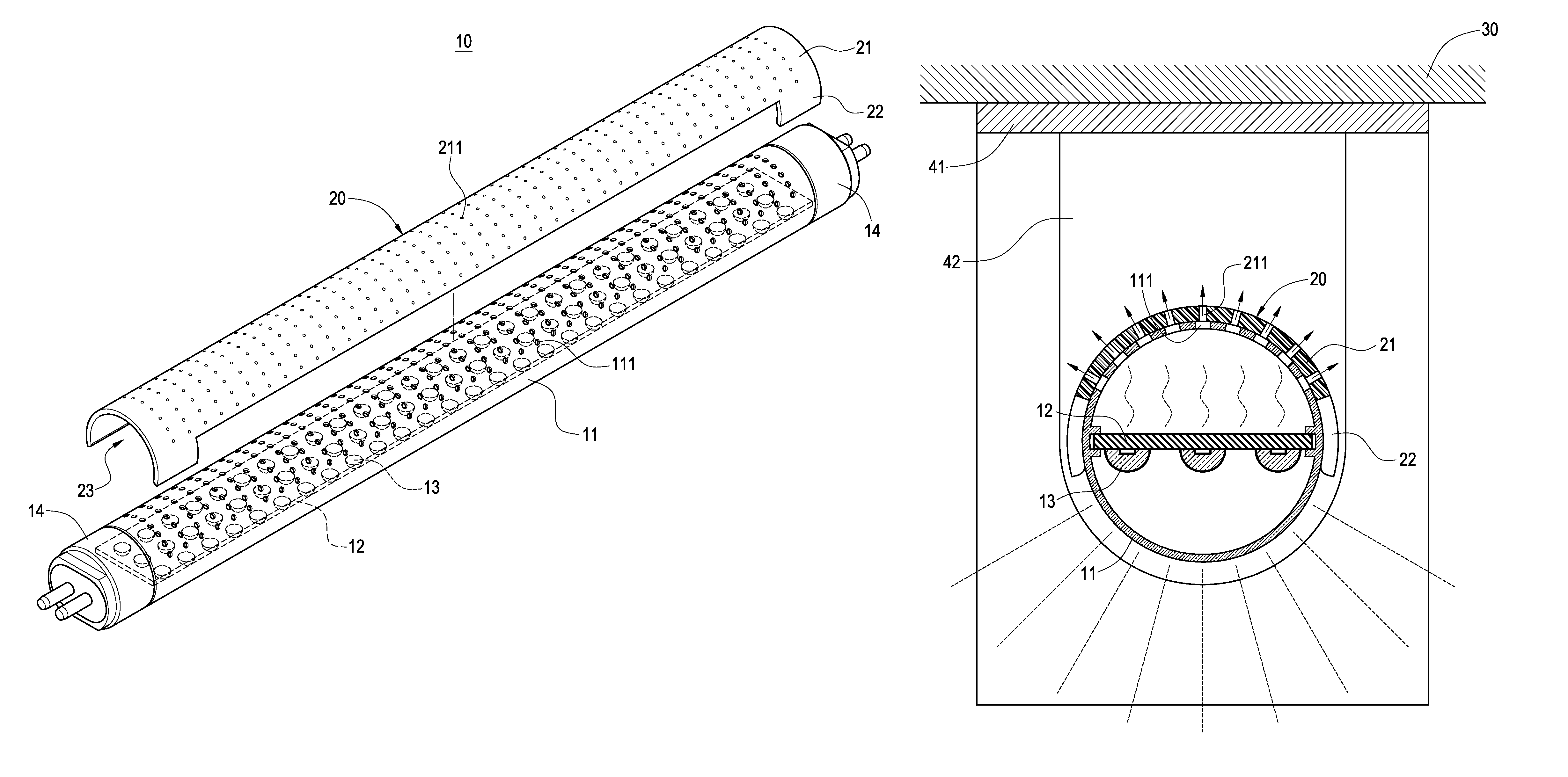
"The invention provides a protecting cover and an LED lamp tube with the protecting cover. The protecting cover has smaller through holes than the LED lamp tube, which allows hot air to pass through and enhance heat dissipation. The protecting cover also prevents bugs from entering the tube and improves its appearance and lifespan. The protecting cover can be easily assembled onto the LED lamp tube using elastic clamps. Overall, the invention improves the performance and lifespan of LED lamp tubes while maintaining their appearance."

Problems solved by technology

However, the conventional LED lamp tube still has the following drawbacks.
Since hot air is produced inside the LED lamp tube and dissipated to the outside through the heat dissipating holes, therefore the air flow speed of the hot air cannot be increased effectively when the hot air passes through the heat dissipating holes, and thus affecting the heat dissipating performance of the LED lamp tube.
Furthermore, bugs such as mosquitoes and flies may enter into the tube directly through the heat dissipating holes and stay on the circuit board, and thus affecting the appearance of the LED lamp tube and reducing the performance and life of the LED lamp tube.

Method used


Image

  • Protecting cover and LED lamp tube having the same
  • Protecting cover and LED lamp tube having the same
  • Protecting cover and LED lamp tube having the same

Examples


Embodiment Construction

[0020]The technical characteristics, features and advantages of the present invention will become apparent in the following detailed description of preferred embodiments with reference to the accompanying drawings, and the preferred embodiments are used for illustrating the present invention only, but not intended to limit the scope of the present invention.

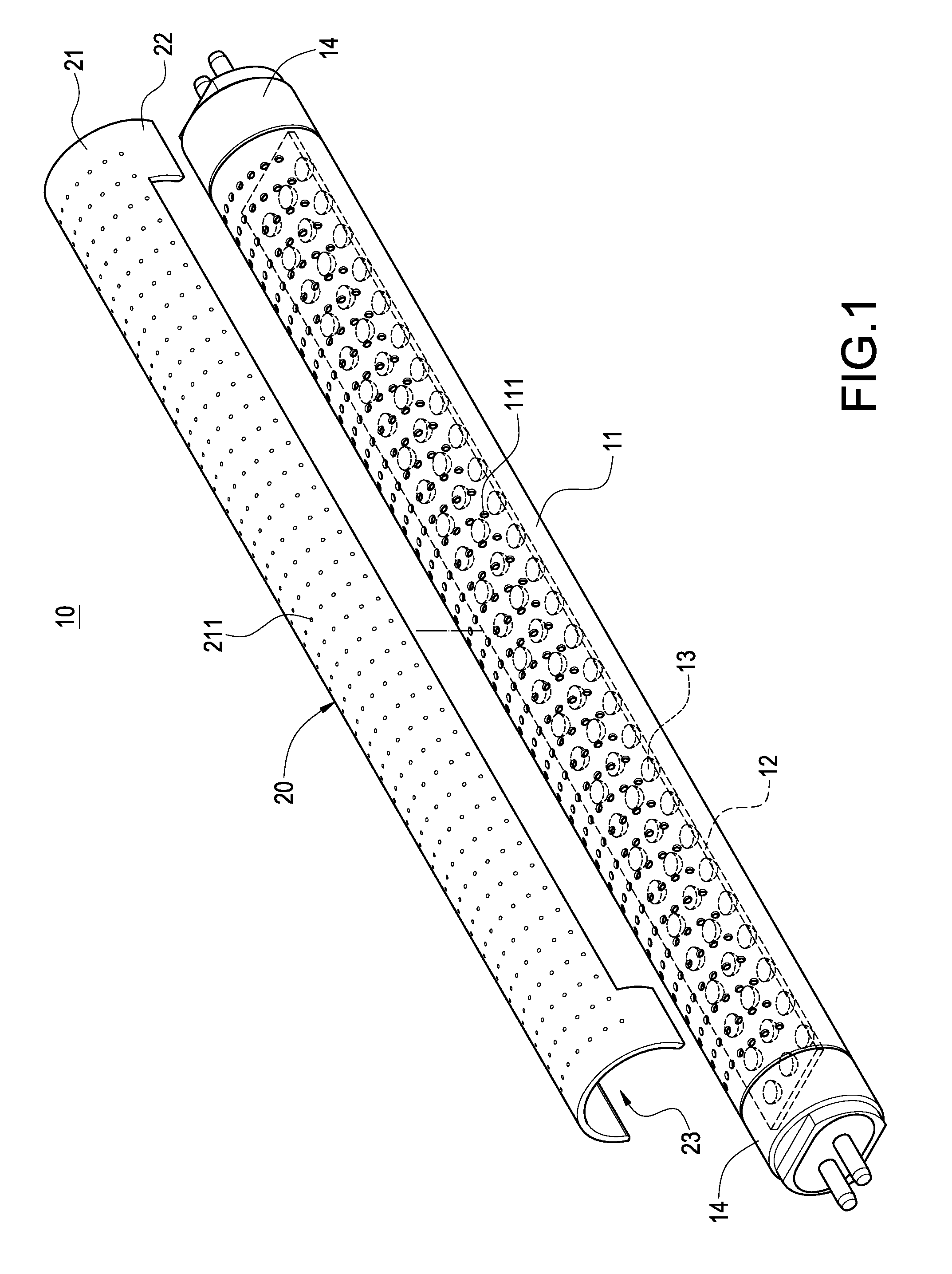
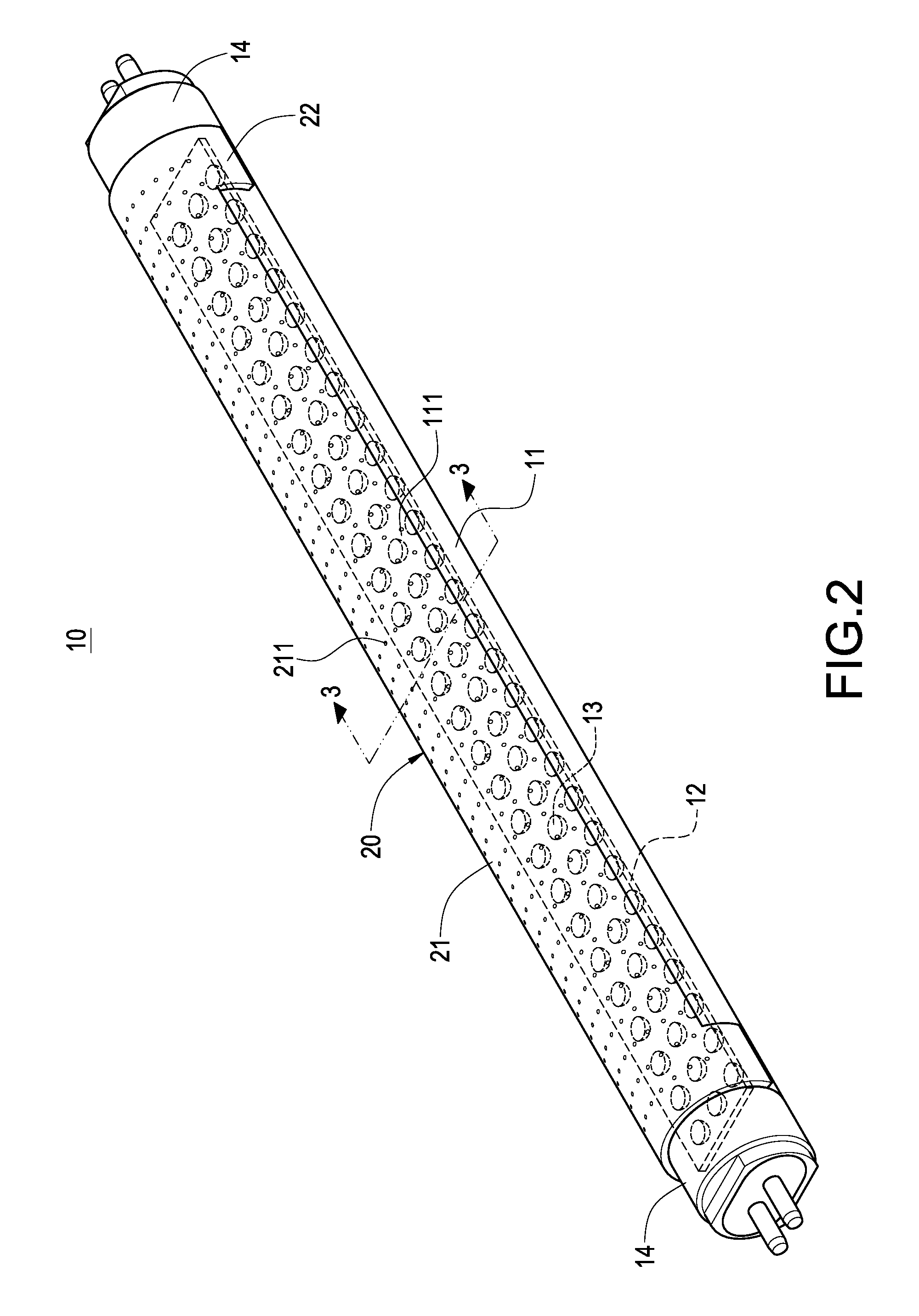
[0021]With reference to FIGS. 1 to 3 for an LED lamp tube 10 in accordance with the present invention, the LED lamp tube 10 comprises a tube 11, a circuit board 12, a plurality of LED lamps 13, two electric connectors 14 and a protecting cover 20.

[0022]The tube 11 is made of a thin and transparent acrylic material, and the tube 11 includes a plurality of heat dissipating holes 111 arranged with an interval apart from each other.

[0023]The circuit board 12 is installed in the tube 11.

[0024]The LED lamps 13 are installed on the circuit board 12 and electrically coupled to the circuit board 12, and the LED lamps 13 are arranged with ...


PUM


Abstract

A light emitting diode (LED) lamp tube structure includes a tube, a circuit board, a plurality of LED lamps, two electric connectors and a protecting cover. The tube includes a plurality of heat dissipating holes. The circuit board is installed in the tube. The LED lamps are installed on the circuit board and electrically coupled to the circuit board. The two electric connectors are connected to both ends of the tube and electrically coupled to the circuit board. The protecting cover is installed onto the LED lamp tube and includes a board, and through holes disposed on the board and corresponding to the heat dissipating holes. Therefore, the LED lamp tube structure achieves a good heat dissipating effect and enhances the life of the LED lamp tube.

Description

BACKGROUND OF THE INVENTION[0001]1. Field of the Invention[0002]The present invention generally relates to a light emitting diode (LED) lamp tube, and more particularly to a protecting cover and an LED lamp tube having the protecting cover.[0003]2. Description of Prior Art[0004]As science and technology advance, electronic products and components tend to be developed with a thin, light, short and compact design, and electronic components such as light emitting diodes (LEDs) are used extensively in illumination equipments due to the advantages of small size, power saving, long life and environmental protection, etc. Although the light emitting diode has encountered a bottleneck of insufficient brightness at an early stage of its development, breakthroughs on related materials and technologies have been made in recent years, and the light emission efficiency of the light emitting diode is improved substantially even up to the brightness of traditional illumination equipments. Therefor...

Claims


Application Information

Patent Timeline
Patent Type & Authority Patents(United States)
IPC IPC(8): F21S4/00F21V29/00F21V29/503F21V29/506F21V29/83
CPCF21K9/00F21K9/17F21V29/83F21V17/04F21V29/507F21Y2101/02F21Y2103/003F21K9/27F21Y2103/10F21Y2115/10F21K9/66
Inventor LIN, KUO-LENLIN, CHEN-HSIANGHSU, KENCHENG, CHIH-HUNG
Owner KITAGAWA HLDG
Learn More