
Photo detector with compensated output and method involving same

a technology of photo detector and output, applied in the field of photo sensors and compensation, can solve the problems of not being used in situations that require repeated operation, silicon cells or sensors, and inability to adapt to the situation

Inactive Publication Date: 2009-10-27
LED ROADWAY LIGHTING +1
View PDF22 Cites 19 Cited by
  • Summary
  • Abstract
  • Description
  • Claims
  • Application Information

AI Technical Summary

Benefits of technology

"The present invention relates to techniques and apparatus for compensating photo sensors and associated photo cells for device and assembly variations, as well as environmental variations, to provide accurate light level readings. The invention addresses the problem of variations in photo sensors, which can result in inaccurate light level readings. The invention provides methods and apparatus for determining or utilizing compensation parameters to provide a compensated signal indicative of an actual or absolute light level, which can enhance and improve control of systems that use photo sensors. The invention can be implemented in various circuits and can be used in various lighting systems and other systems that use photo sensors for control."

Problems solved by technology

Cadmium Sulphide based sensors or cells are typically available as light dependent resistors that advantageously resemble a human eye response to light, however suffer from an irreversible drift with temperature and thus have not been used in situations that require repeated operation, i.e., light detection.
Silicon cells or sensors while having long life expectancies and good sensitivities and being available in small sizes have various problems.
These variations are not acceptable in some situations where accurate light levels are required.
One technique, for overcoming variations due to temperature is to control the temperature of the photo cell, however controlling temperature comes with its own set of difficulties, e.g., hardware costs in terms of size and economics.

Method used


Image

  • Photo detector with compensated output and method involving same
  • Photo detector with compensated output and method involving same
  • Photo detector with compensated output and method involving same

Examples


Embodiment Construction

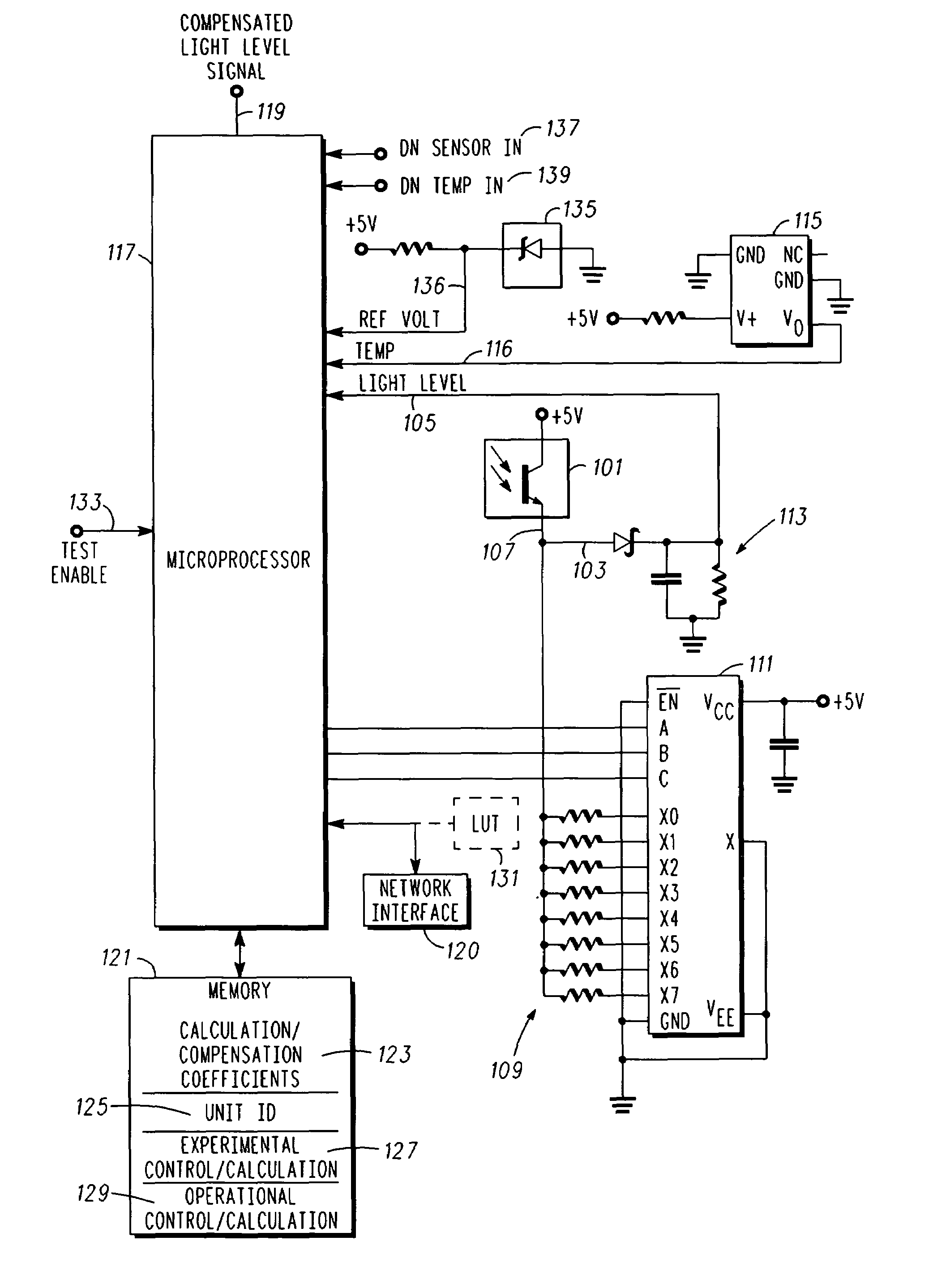
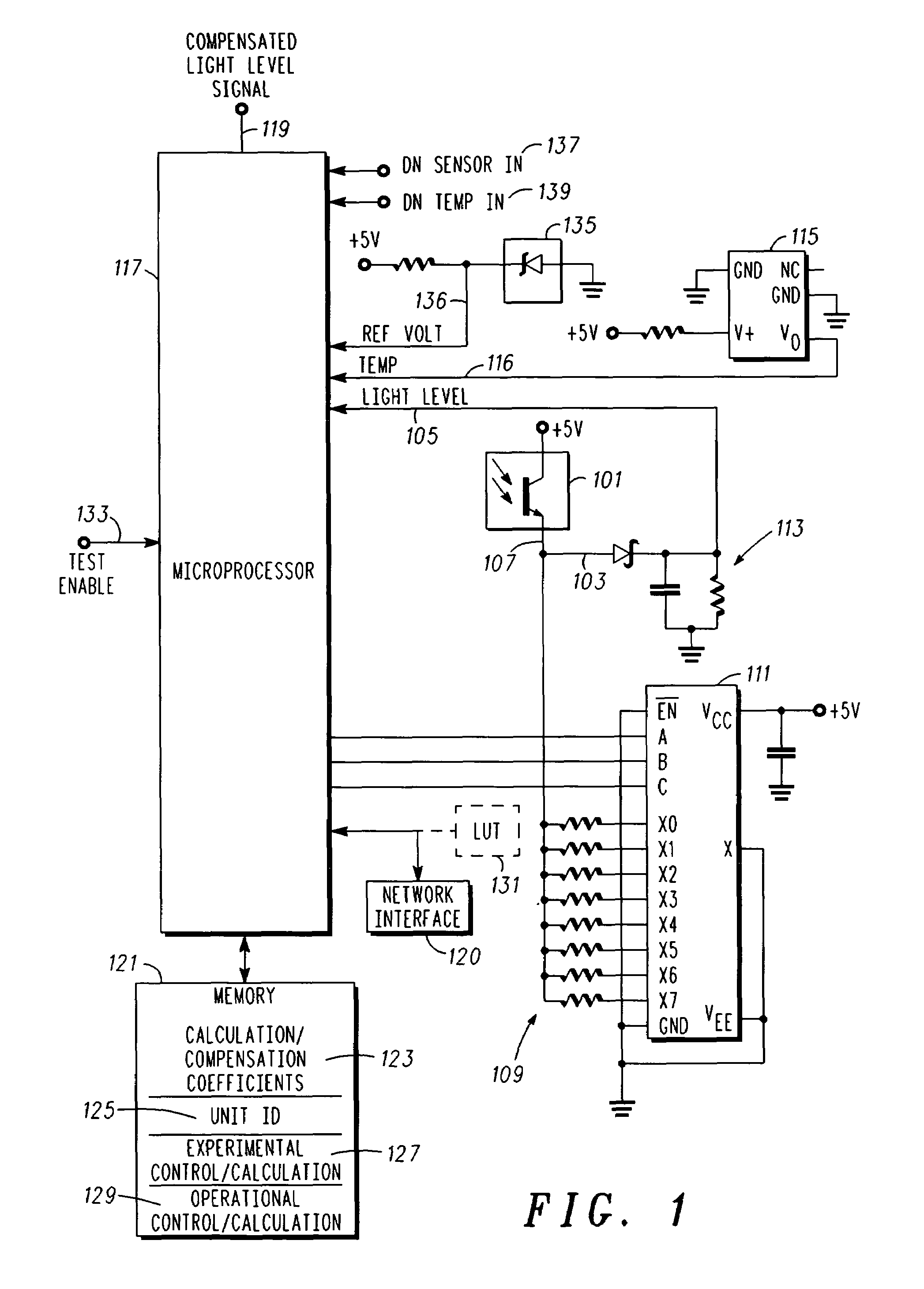
[0011]In overview, the present disclosure concerns accurate light level sensing using, e.g., a photo sensor, and more specifically techniques and apparatus for compensating such photo sensors and associated photo cells for device and assembly variations as well as environmental variations in order to provide accurate light level readings. The photo sensors are typically arranged and constructed for facilitating control of other systems, e.g., lighting systems and the like, where ambient light levels or actual light levels, e.g., from an associated lamp or the like, may be used pursuant to control of the associated system. More particularly various inventive concepts and principles embodied in methods and apparatus, for determining or utilizing compensation parameters or coefficients to provide a compensated signal indicative of an actual or absolute light level will be discussed and disclosed.

[0012]The systems of particular interest may vary widely but include outdoor and indoor lig...


PUM


Abstract

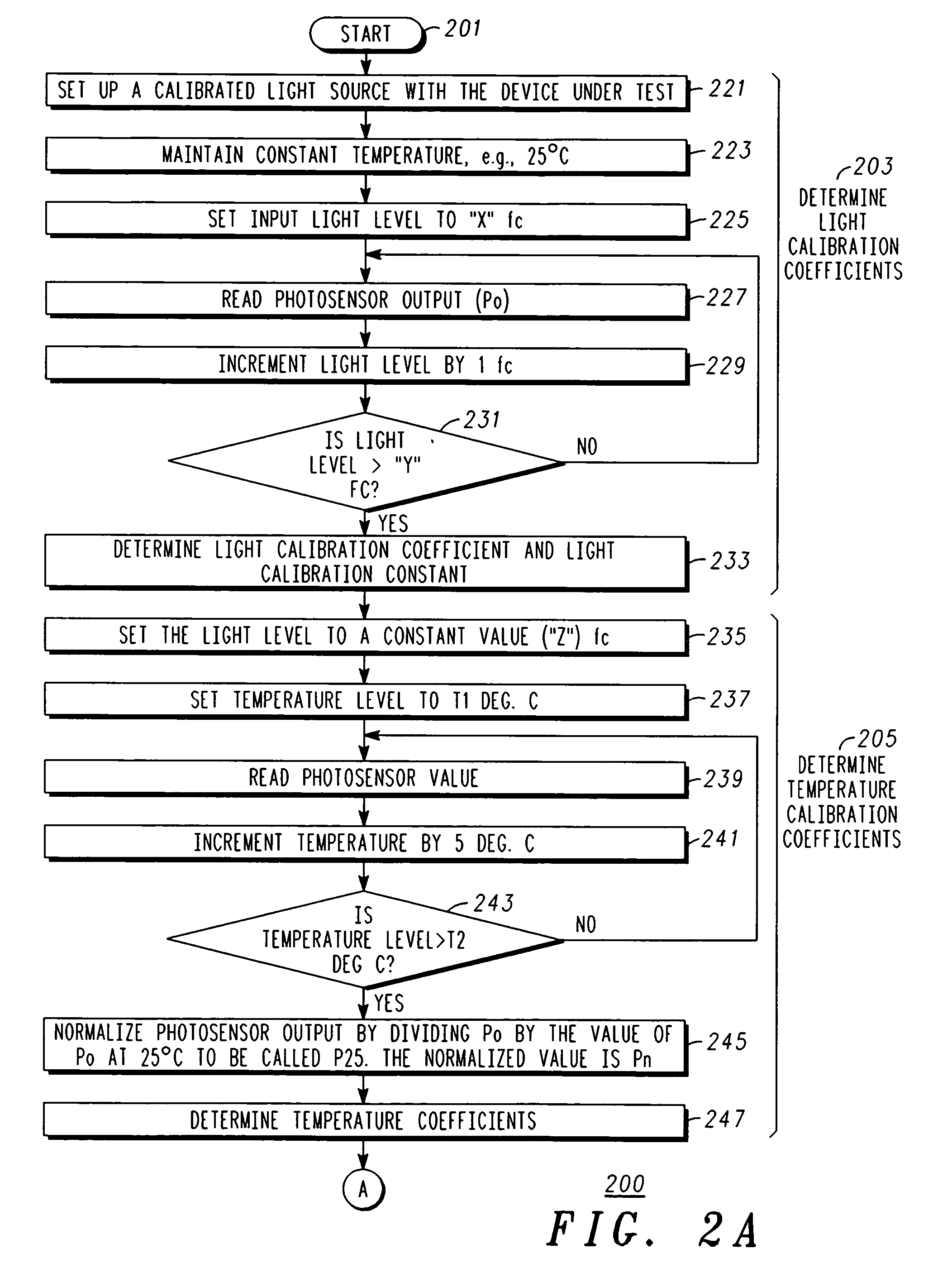
A method of compensating a photo sensor (and a corresponding photo sensor with compensation) insures the accuracy of the photo sensor, e.g., over environmental variations or photo cell variations. The method comprises: providing a first signal indicative of a light level; providing a second signal indicative of an environmental parameter, e.g., temperature; and calculating, responsive to the first signal and the second signal, a compensated signal that is indicative of an absolute light level. The calculating can be performed by a processor and utilize calibration and compensation information or parameters, which can be obtained experimentally.

Description

RELATED APPLICATIONS[0001]This application claims priority from Provisional Application, Ser. No. 60 / 695,252, filed on Jun. 30, 2005 and Provisional Application, Ser. No. 60 / 695,627, filed on Jun. 30, 2005, which are each hereby incorporated herein in their entirety by reference.FIELD OF THE INVENTION[0002]This invention relates in general to photo sensors and compensation of such photo sensors and more specifically to techniques and apparatus for applying compensation to signals obtained from a photo cell used in a photo sensor.BACKGROUND OF THE INVENTION[0003]Photocells and associated circuitry (photo sensor) for converting light levels into an electrical signal are known. Photo sensors are used, for example, to control street lights and the like such that the lights are turned off during day time and on at night.[0004]Photo sensors and specifically photocells come in various technologies, e.g., Silicon and Cadmium Sulphide. Cadmium Sulphide based sensors or cells are typically av...

Claims


Application Information

Patent Timeline
Patent Type & Authority Patents(United States)
IPC IPC(8): H01J40/14
CPCH01L31/02019
Inventor SHARMA, PRATIBHAKURZ, GERALD E.CHO, YONG JEONGANDERSON, JAMES A.ANDERSON, J. DAVID T.JACKLIN, GREGORY A.
Owner LED ROADWAY LIGHTING
Learn More