Automobile side airbag guide plate
a technology for side airbags and guide plates, which is applied in the direction of pedestrian/passenger safety arrangements, vehicular safety arrangments, vehicle components, etc., can solve the problems of preventing the smooth affecting the safety of passengers, so as to achieve rapid and stable deployment of airbag tubes
- Summary
- Abstract
- Description
- Claims
- Application Information
AI Technical Summary
Benefits of technology
Problems solved by technology
Method used
Image
Examples
first exemplary embodiment
[0064]Hereinafter, a first exemplary embodiment of the present invention will be described with reference to FIGS. 3 to 6.
[0065]As shown in FIG. 3, an airbag module 10 in accordance with the present invention is supported at its lower surface by a support bracket 100 fixed to an inner panel 6 between a roof panel (not shown) and a head liner 4.
[0066]Since the airbag module 10 is similar to the conventional art, a detailed description thereof will be omitted. Hereinafter, a pair of support brackets 100 not found in the conventional art will be described in detail.
[0067]The pair of support brackets 100 are disposed at both sides of a center pillar 2 and fixed to an inner panel 6 disposed between a roof panel and a head liner 4. The fixed support brackets 100 have a length corresponding to an inner side body of the automobile.
[0068]As shown in FIG. 4, the support bracket 100 has an approximate “L” shape, which includes a vertical part 110 and a horizontal support part 120.
[0069]The ver...
second exemplary embodiment
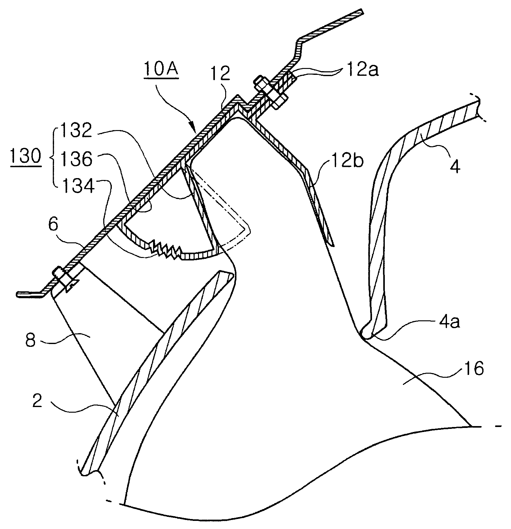
[0079]Hereinafter, a second exemplary embodiment in accordance with the present invention will be described with reference to FIGS. 7 to 10.
[0080]An airbag module 10A has an airbag housing 12 in which an airbag tube 16 is disposed. The airbag housing 12 has a mounting part 12a bolted to a chassis, i.e., an inner panel 6, between a roof panel (not shown) and a head liner 4.
[0081]The airbag housing 12 bolted to the inner panel 6 is disposed adjacent to a boundary between a center pillar 2 and the head liner 4.
[0082]In addition, the airbag housing 12 has a door 12b installed at its one surface opposite to the head liner 4 and opened by the inflating airbag tube 16.
[0083]Further, the door 12b is detached and opened from the housing 12 at its lower end when the airbag tube 16 is deployed. The door 12b has a tear line 13a having an approximately “V” shape groove and formed along the lower end and both side ends to facilitate detachment of the door 12b.
[0084]Furthermore, the airbag housin...
third exemplary embodiment
[0100]Hereinafter, a third exemplary embodiment in accordance with the present invention will be described with reference to FIGS. 11 to 14.
[0101]As shown in FIGS. 11 to 14, an airbag module 10C of the third exemplary embodiment includes an airbag tube 16 folded several times therein, an airbag housing 12, in which the airbag tube 16 is disposed, the airbag housing 12 having a door 12b formed at its one side and a mounting part 12a fixed to an inner panel 6 through a bolt at its upper end, and an inflator 20 connected to a rear end of the airbag tube 16 to inject a large amount of high-pressure gas thereinto.
[0102]In this process, as shown in FIGS. 11 and 12, the side airbag guide plate in accordance with the present invention resiliently supports a bottom surface of the airbag housing 12 of the airbag module 10C to stably guide the airbag tube into the automobile when the airbag tube 16 inflates.
[0103]In addition, the guide plate 140 is formed of a metal material, and has insertion...
PUM
 Abstract
Description
Claims
Application Information
 - R&D
- Intellectual Property
- Life Sciences
- Materials
- Tech Scout
- Unparalleled Data Quality
- Higher Quality Content
- 60% Fewer Hallucinations
Browse by: Latest US Patents, China's latest patents, Technical Efficacy Thesaurus, Application Domain, Technology Topic, Popular Technical Reports.
© 2025 PatSnap. All rights reserved.Legal|Privacy policy|Modern Slavery Act Transparency Statement|Sitemap|About US| Contact US: help@patsnap.com


