
Automobile side airbag guide plate

a technology for side airbags and guide plates, which is applied in the direction of pedestrian/passenger safety arrangements, vehicular safety arrangments, vehicle components, etc., can solve the problems of preventing the smooth affecting the safety of passengers, so as to achieve rapid and stable deployment of airbag tubes

Inactive Publication Date: 2007-04-26
AUTOLIV DEV AB
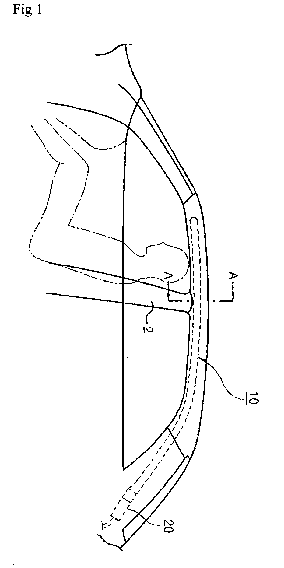
View PDF7 Cites 34 Cited by
  • Summary
  • Abstract
  • Description
  • Claims
  • Application Information

AI Technical Summary

Benefits of technology

[0031] An object of the present invention is to provide an automobile side airbag guide plate enabling rapid and stable deployment of an airbag tube into the automobile, by forming a support bracket for supporting an airbag module between a roofpanel and a head liner and rapidly opening the head liner using the support bracket when the airbag tube is deployed, thereby protecting a driver / passenger from injury by banging against the side of the automobile in a collision
[0032] Another object of the present invention is to provide an automobile side airbag guide plate enabling rapid and stable deployment of an airbag tube into the automobile to protect the driver / passenger from injury in a collision, by forming a shock absorption part formed of an air layer, rather than a guide plate, at a lower surface of an airbag housing to prevent damage of the airbag housing when the airbag tube is deployed.
[0033] Still another object of the present invention is to provide an automobile side airbag guide plate capable of supporting a lower surface of an airbag housing, and rapidly and stably guiding an airbag tube into the automobile when the airbag tube is deployed
[0034] Yet another object of the present invention is to provide an automobile side airbag guide plate capable of obtaining a more stable deployment angle of a door of an airbag housing on initial deployment of an airbag tube through a bent part formed at a bottom surface of a guide plate, and absorbing impact using the bent part.
[0035] Yet another object of the present invention is to provide an automobile side airbag guide plate enabling orderly deployment of a side airbag without interference by a center pillar.

Problems solved by technology

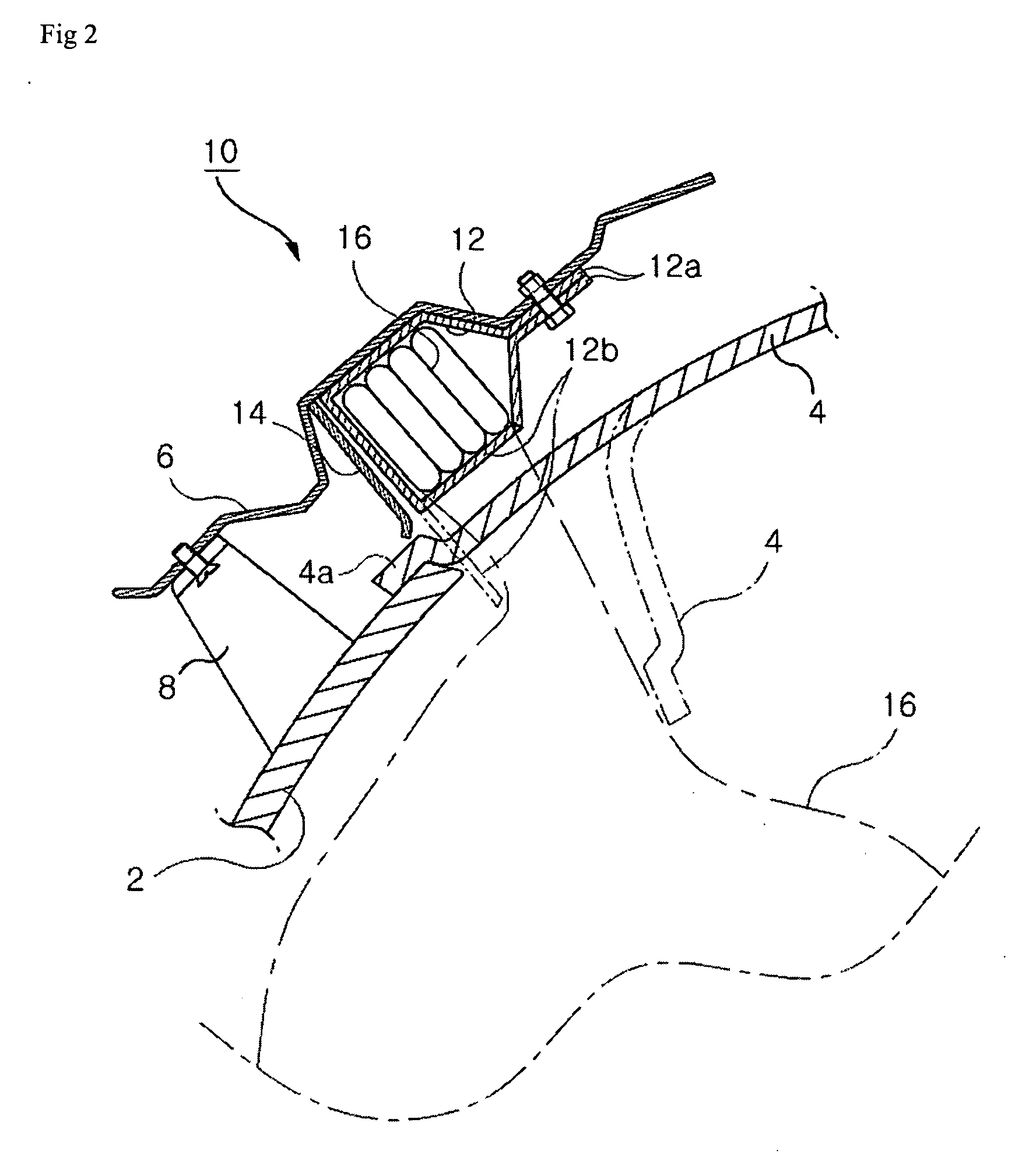
As a result, the head liner 4 around the center pillar 2 cannot be smoothly opened thereby hindering smooth deployment of the airbag tube 16 and endangering the driver / passenger.
However, since the guide plate 14 rotated with the lower surface of the housing 12 has a simple plate shape which is not very strong, it may be broken due to gas pressure when the airbag tube 16 is deployed, rather than being in contact with the inner panel 6 to absorb shock.
Further, it is not possible to replace a broken guide plate 14.
Another problem with the side airbag is that an inner guide may be deformed due to external impact, and since there is no auxiliary guide member at both sides of the side airbag, deployment of the airbag may be obstructed.

Method used


Image

  • Automobile side airbag guide plate
  • Automobile side airbag guide plate
  • Automobile side airbag guide plate

Examples


first exemplary embodiment

[0059] Hereinafter, a first exemplary embodiment of the present invention will be described with reference to FIGS. 3 to 6.

[0060] As shown in FIG. 3, an airbag module 10 in accordance with the present invention is supported at its lower surface by a support bracket 100 fixed to an inner panel 6 between a roof panel (not shown) and a head liner 4.

[0061] Since the airbag module 10 is similar to the conventional art, a detailed description thereof will be omitted. Hereinafter, a pair of support brackets 100 not found in the conventional art will be described in detail.

[0062] The pair of support brackets 100 are disposed at both sides of a center pillar 2 and fixed to an inner panel 6 disposed between a roof panel and a head liner 4. The fixed support brackets 100 have a length corresponding to an inner side body of the automobile.

[0063] As shown in FIG. 4, the support bracket 100 has an approximate “L” shape, which includes a vertical part 110 and a horizontal support part 120.

[00...

second exemplary embodiment

[0074] Hereinafter, a second exemplary embodiment in accordance with the present invention will be described with reference to FIGS. 7 to 10.

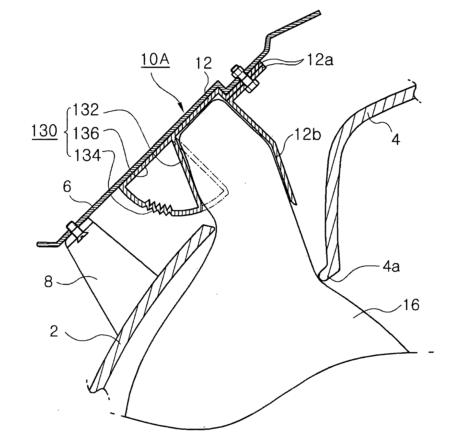
[0075] An airbag module 10A has an airbag housing 12 in which an airbag tube 16 is disposed. The airbag housing 12 has a mounting part 12a bolted to a chassis, i.e., an inner panel 6, between a roof panel (not shown) and a head liner 4.

[0076] The airbag housing 12 bolted to the inner panel 6 is disposed adjacent to a boundary between a center pillar 2 and the head liner 4.

[0077] In addition, the airbag housing 12 has a door 12b installed at its one surface opposite to the head liner 4 and opened by the inflating airbag tube 16.

[0078] Further, the door 12b is detached and opened from the housing 12 at its lower end when the airbag tube 16 is deployed. The door 12b has a tear line 13a having an approximately “V” shape groove and formed along the lower end and both side ends to facilitate detachment of the door 12b.

[0079] Furthermore, the air...

third exemplary embodiment

[0095] Hereinafter, a third exemplary embodiment in accordance with the present invention will be described with reference to FIGS. 11 to 14.

[0096] As shown in FIGS. 11 to 14, an airbag module 10C of the third exemplary embodiment includes an airbag tube 16 folded several times therein, an airbag housing 12, in which the airbag tube 16 is disposed, the airbag housing 12 having a door 12b formed at its one side and a mounting part 12a fixed to an inner panel 6 through a bolt at its upper end, and an inflator 20 connected to a rear end of the airbag tube 16 to inject a large amount of high-pressure gas thereinto.

[0097] In this process, as shown in FIGS. 11 and 12, the side airbag guide plate in accordance with the present invention resiliently supports a bottom surface of the airbag housing 12 of the airbag module 10C to stably guide the airbag tube into the automobile when the airbag tube 16 inflates.

[0098] In addition, the guide plate 140 is formed of a metal material, and has in...


PUM


Abstract

Provided is an automobile side airbag guide plate including support brackets disposed at both sides of a center pillar, fixed to an inner panel between a roof panel and a head liner, and supporting a lower part of an airbag module, wherein each of the support brackets includes a vertical part fixed to the inner panel between the roof panel and the head liner, and a horizontal support part extending from the vertical part to support the lower part of the airbag module fixed to the inner panel.

Description

BACKGROUND OF THE INVENTION [0001] 1. Field of the invention [0002] The present invention relates to an automobile side airbag guide plate, and more particularly, to an automobile side airbag guide plate enabling stable deployment of a side airbag installed between a roof panel and a head liner into the automobile upon collision. [0003] 2. Description of the Prior Art [0004] An automobile airbag, like a safety belt, is a device for protecting a driver / passenger from injury in a collision. [0005] Airbags may be installed in the steering wheel in front of the driver seat, in the glove box in front of the passenger seat, and at both sides of the automobile, i.e., between head liners adjacent to doors and roof panels. The airbags, along with safety belts, function using a collision detection sensor and an electronic control unit (ECU) to protect passengers in a collision. [0006] In a collision, the collision detection sensor outputs a detection signal to the ECU, the ECU activates the a...

Claims


Application Information

Patent Timeline
Patent Type & Authority Applications(United States)
IPC IPC(8): B60R21/213B60R21/20
CPCB60R21/213B60R21/215B60R21/217B60R21/232B60R2021/21518
Inventor JANG, MYUNG-RYUNYOO, BYOUNG-SUNKIM, TAE-WOOLEE, DONG-JUNOH, EUN-HWANCHOI, KYUN-SOONKIM, JUNG-HAN
Owner AUTOLIV DEV AB
Learn More