
Container cap

a container cap and cap body technology, applied in the field of container caps, can solve the problems of imposing limitations on improving the opening/closing performance and improving the touch feeling, so as to improve the touch feeling, and improve the opening/closing performan

Active Publication Date: 2009-10-27
JAPAN CROWN CORK CO LTD
View PDF15 Cites 33 Cited by
  • Summary
  • Abstract
  • Description
  • Claims
  • Application Information

AI Technical Summary

Benefits of technology

[0007]According to JP-A-2001-354247, heights of the large protuberances and small protuberances, and a pitch between the large protuberance and the small protuberance, are adjusted to improve opening / closing performance of the container cap as well as to improve the touch feeling at the time of opening and closing. With the shape in which the large protuberances and the small protuberances are alternately arranged, however, limitation is imposed on improving the opening / closing performance and improving the touch feeling.
[0008]The present invention was accomplished in view of the above circumstances and its object is to provide a container cap which offers improved opening / closing performance and improved touch feeling.

Problems solved by technology

If a difference in the height is large between the large protuberances and the small protuberances, on the other hand, tough feeling (contact feeling) will often be such that the ends of the large protuberances bite into the inner surfaces of the fingers at the time of opening or closing the container cap causing a pain.
With the shape in which the large protuberances and the small protuberances are alternately arranged, however, limitation is imposed on improving the opening / closing performance and improving the touch feeling.

Method used


Image

  • Container cap
  • Container cap
  • Container cap

Examples


first embodiment

[0023]A container cap according to the present invention will now be described with reference to the drawings.

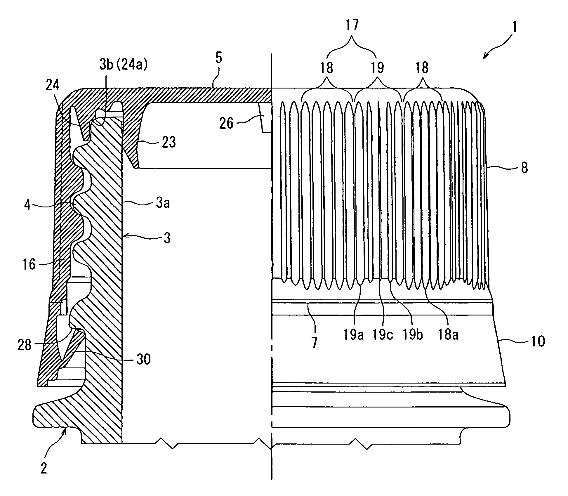
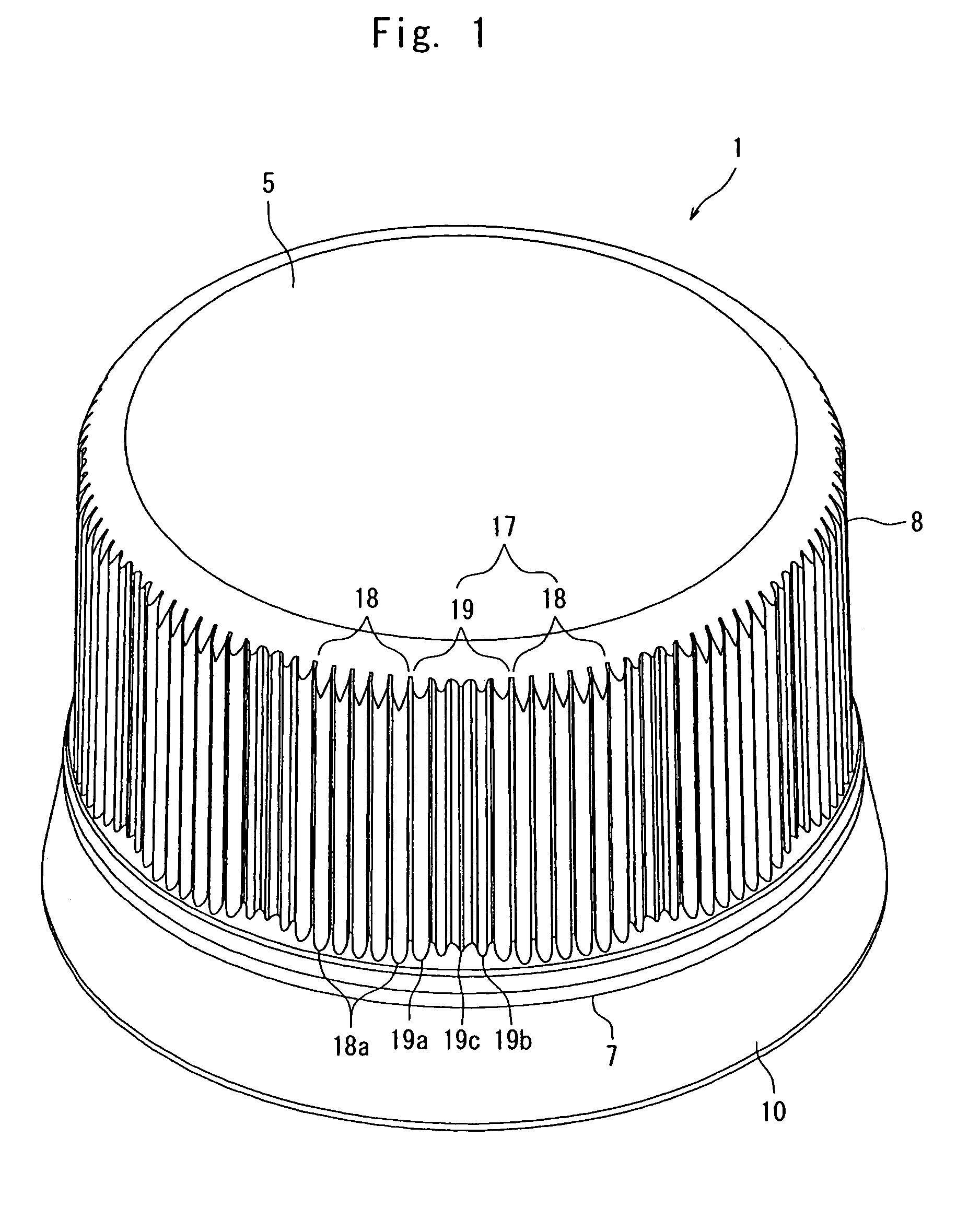
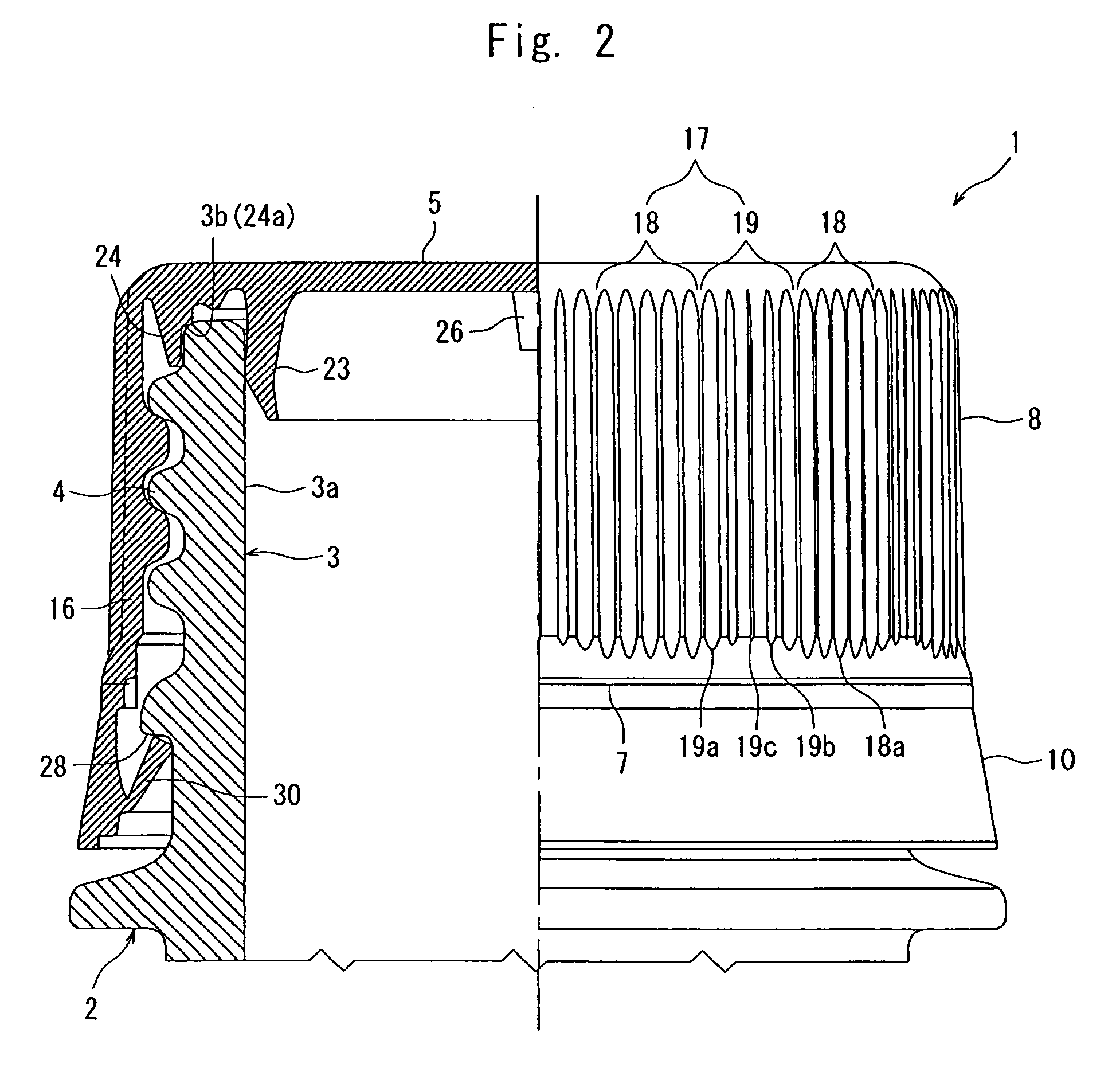
[0024]FIG. 1 is a perspective view of a container cap 1 according to the present invention, and FIG. 2 is a view wherein the right side of the center line is a front view of the container cap 1 and the left side is a sectional view of the container cap 1.

[0025]The container cap 1 is formed by using a synthetic resin such as polyethylene or polypropylene. The container cap 1 has a top panel wall 5 of the shape of a disk and a skirt wall 6 of nearly a cylindrical shape hanging down from the circumferential edge of the top panel wall 5. The circular top panel wall 5 of the container cap 1 extends as a whole substantially horizontally, and a weakened line 7 is formed in the lower part of the skirt wall 6 extending in the circumferential direction. The skirt wall 6 has a main portion 8 over the weakened line 7 and a tamper-evidence hem 10 under thereof.

[0026]The circumferential w...

second embodiment

[0041]Next, the invention will be described.

[0042]FIG. 6 is a side view of the container cap according to a second embodiment, and FIG. 7 is a sectional view of the container cap in the direction of a line Y-Y in FIG. 6, omitting the top panel wall. The same portions as those of the above embodiment are denoted by the same reference numerals.

[0043]In the above first embodiment as shown in FIG. 3, threaded portions 21a are formed in the internal thread 21 so as to be corresponded to the small protuberance regions 19 and missing portions 21b are formed in the internal thread 21 so as to be corresponded to the large protuberance regions 18 having a large rigidity to maintain balance in the strength of the container cap 1.

[0044]However, in case, when, for example, the thread is turned by 1.5 turns in the circumferential direction, there occur a portion where the internal threads are present being overlapped in the up-and-down direction and a portion where the internal thread is simply p...


PUM


Abstract

A container cap which offers improved opening / closing performance and improved touch feeling. Linear protuberances are formed on the circumferential wall of the main portion of the skirt of the container cap of the container. The protuberances include large protuberances having a large height and small protuberances having heights of protrusion from the outer surface of the circumferential wall portion smaller than that of the large protuberances. The main portion has large protuberance regions forming a plurality of large protuberances and small protuberance regions forming a plurality of small protuberances, the large protuberance regions and the small protuberance regions being alternately arranged in the circumferential direction of the main portion.

Description

BACKGROUND OF THE INVENTION[0001]1. Field of the Invention[0002]The present invention relates to a container cap which is fitted to the mouth-and-neck portion of a container containing such a liquid as a beverage, a detergent or a chemical agent, and which offers good touch feeling at the time when it is to be opened or closed.[0003]2. Description of the Related Art[0004]A container cap of a container for containing coffee or carbonated beverage has linear protuberances (vertical ribs, often called knurling in this field of art) extending in the up-and-down direction and formed on the so-called skirt wall corresponding to the circumferential wall portion of a cylindrical shape with bottom. The protuberances are so formed that the fingers will not slip at the time of opening or closing the container cap.[0005]Protuberances of the same shape and of the same height are usually formed on the container cap. For easier opening and closing of the container cap, however, a technology has be...

Claims


Application Information

Patent Timeline
Patent Type & Authority Patents(United States)
IPC IPC(8): B65D41/00B65D41/34B65D41/04
CPCB65D41/3428B65D41/0485B65D41/34B65D41/04
Inventor KUMATA, MITSUOMATSUTANI, HIROOMITOMITAKA, YUJI
Owner JAPAN CROWN CORK CO LTD
Learn More