Conduit guide clip

a guide clip and clip technology, applied in the field of clips, can solve the problems of difficult to see the hole in the handlebar for receiving the post, the difficulty of coiled wires, and the difficulty of reducing the service life of the wire, so as to facilitate the attachment and facilitate the use. , the effect of economic and durabl

Active Publication Date: 2009-10-27
WESCON CONTROLS
View PDF31 Cites 9 Cited by
  • Summary
  • Abstract
  • Description
  • Claims
  • Application Information

AI Technical Summary

Benefits of technology

[0010]These and other objects have largely been met by the conduit guide clip of the present invention. That is to say, the conduit guide clip hereof presents an article which can be molded of synthetic resin as a unitary member, is economical and durable, provides a relatively rigid attachment to a handlebar or other tubular support, and facilitates attachment by the installer, preferably by enabling the guide clip to substantially slide onto the tubular support. Furthermore, the guide clip hereof resists movement relative to the handlebar during normal operation when shifting of the cable may result in a moment arm between a receiver for the control cable and the longitudinal axis of the handlebar.
[0012]As a result, the guide clip hereof may be more easily be mounted to the handlebar or other tubular support than conventional guide clips, without the need for tools, while still remaining economical, durable in use, and provided a relatively rigid and fixed mounting location for the control cable. In the first instance, it is relatively easy for the installer to visually track the mounting post as it enters a complementally configured receiving hole in the tubular support. By first locating the mounting post in the receiving hole, the guide clip is initially at an acute angle relative to the longitudinal axis of the tubular support. The exposed aspect of the guide clip, having only one clasping arm which has a swept remote edge and a front edge rearward of and which does not intersect a plane extending longitudinally from the post, enables the user to insert the mounting post, which preferably extends substantially diametrically through two opposed openings in the arcuate wall of the tubular handlebar without interference. The guide clip is then easily installed by simply pivoting the guide clip on the mounting post whereby the handlebar snaps into place between the arm and the cable receiver. Thus, the longitudinal axis of the cable receiver is substantially parallel to the longitudinal axis of the handlebar to reduce torsional forces. When the cable is actuated, most of the forces imparted by the cable to the clip are parallel to the axis of the handlebar. The arm and cable receiver help to resist dislodgement of the guide clip, and the mounting post resists movement longitudinally along the longitudinal axis of the handlebar as well as rotational movement of the guide clip in a circumferential direction around the handlebar.
[0013]During mounting of the guide clip, the arm, being flexible, yields more readily because of the swept remote edge, and requires less force to spread the arm until the handlebar or other tubular support is fully seated against the inner surface of the receiver. Thus, the guide clip hereof requires less force to attach to a tubular support than conventional structures for holding a conduit in place, and preferably largely slides into the desired coupled position. In this position, an arcuate inner surface of the receiver of the guide clip lies against the tubular support with the passage of the receiver substantially parallel to the longitudinal axis of the tubular support, while the single arm wraps around and essentially enfolds and clamps the tubular support to the receiver and resist dislodgement. The mounting post, being fully received in the hole of the tubular support and of a length sufficient to extend diametrically therethrough, resists relative circumferential movement as well as relative axial movement between the guide clip and the tubular support.

Problems solved by technology

One challenge presented in the design of products having a control mechanism positioned remotely from a controllable mechanism such as an engine throttle or clutch is the routing of the control cable connecting the control and the controllable mechanism.
While a simple and elegant solution, the coiled wire presents economic challenges when the cable is supplied separately and must be inserted into the coil at a later date.
While this system provides a unitary member for positioning the cable which may be mounted to a handlebar, considerable force may be required to spread the flanges and the hole in the handlebar for receiving the post is not readily visible during the attachment of the system to the handlebar.

Method used


Image

  • Conduit guide clip
  • Conduit guide clip
  • Conduit guide clip

Examples


Embodiment Construction

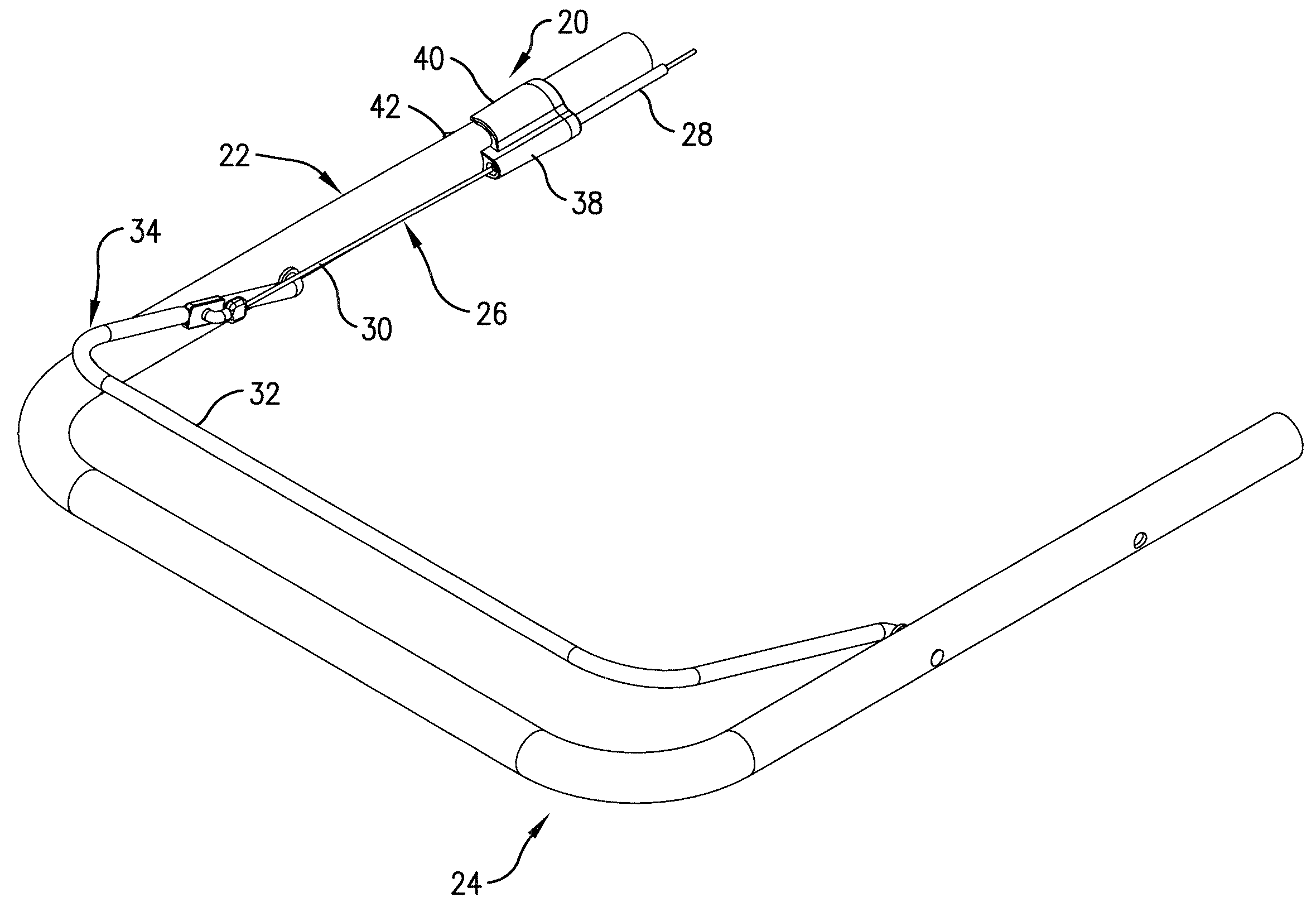
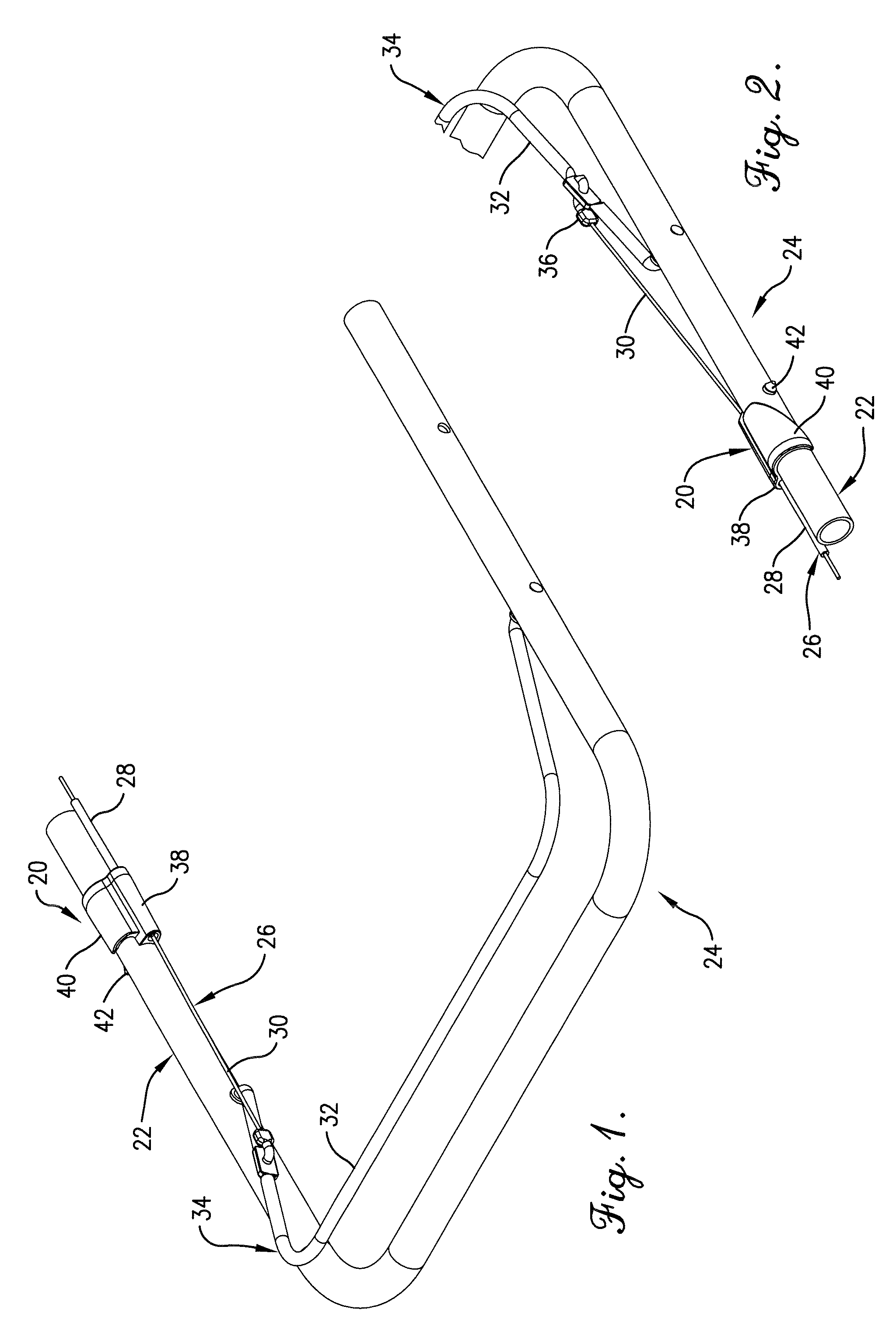
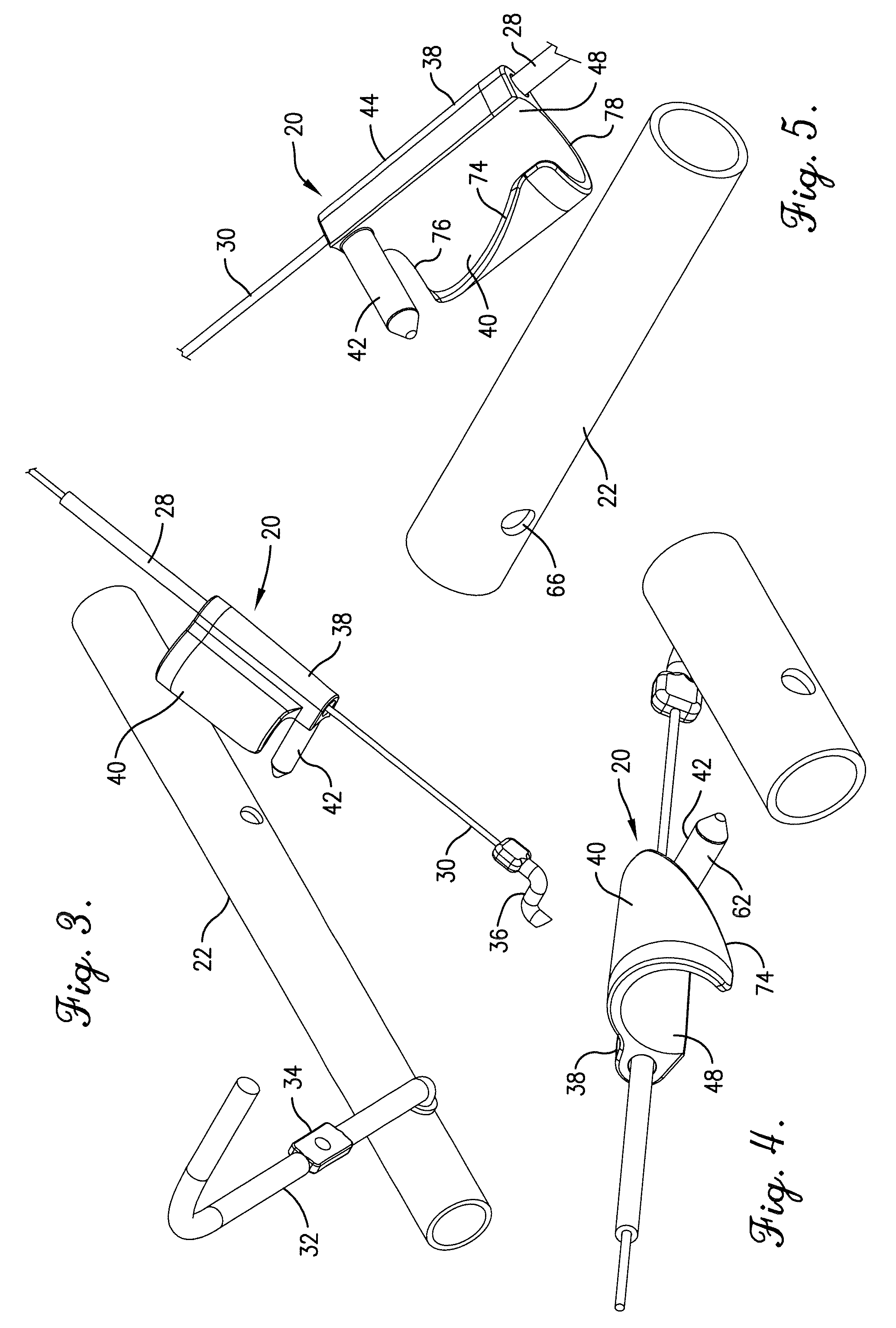
[0025]Referring now to the drawings, a conduit guide clip 20 in accordance with the present invention is shown in FIG. 1 mounted to a tubular support 22 such as a handlebar of a walk-behind lawn mower 24 or other powered equipment (e.g., a tiller, aerator, or the like) having a controllable member. The mower 24 is provided with a control cable system 26, provided as a Bowden cable having a sheath 28 and a control cable 30, and the control cable 30 extends between a remote end operatively connected to the controllable member such as an engine throttle, clutch or the like and a proximate end which is operatively connected to a control 34 which is preferably also mounted to the tubular support. The control 34 has a shiftable member 32 to which a proximate end 36 of the control cable 30 is attached for actuating the controllable member. In the drawings shown herein, the control 34 is shown as a deadman bail of a lawn mower, with the bail pivotally mounted to the mower to actuate a blade...


PUM


Abstract

A conduit guide clip is provided which includes a receiver and a single arm extending therefrom is provided for mounting to a tubular support such as the handlebar of a walk-behind lawn mower. The guide clip further includes a mounting post, which is inserted into a hole in the tubular support. The arm is curved to wrap around and clamp an arcuate inner surface of the receiver against the tubular support after installation. The mounting post is positioned to extend from the arcuate inner surface, and the arm includes a rearwardly swept remote edge and located whereby no portion of the arm is positioned to intersect the longitudinal axis of the mounting post.

Description

BACKGROUND OF THE INVENTION[0001]1. Field of the Invention[0002]The present invention concerns a clip intended for mounting to a handlebar or the like to guide and inhibit fouling of control cables. More particularly, it is concerned with a guide clip which may be molded into a unitary member and facilitates easy mounting to a handlebar and retention in its desired location by a mounting post positioned generally axially forward of the portion of the swept and arcuate leading edge of an attachment arm which, absent such a swept characteristic, would otherwise be opposite to the mounting post.[0003]2. Description of the Prior Art[0004]One challenge presented in the design of products having a control mechanism positioned remotely from a controllable mechanism such as an engine throttle or clutch is the routing of the control cable connecting the control and the controllable mechanism. Because the control cable is flexible and may need to extend a considerable distance, there is often...

Claims


Application Information

Patent Timeline
Patent Type & Authority Patents(United States)
IPC IPC(8): F16C1/26
CPCA01D34/824F16C1/262G05G1/04A01D2034/6843Y10T74/20287Y10T74/20402Y10T403/7015Y10T74/20456Y10T74/20462F16C2310/00
Inventor COX, MARVINBEUGELSDYK, ANTHONY F.
Owner WESCON CONTROLS
Why Eureka
Try Eureka