
Barrel attachment for gas gun

a barrel attachment and gas gun technology, applied in the direction of compressed gas guns, white arms/cold weapons, weapons, etc., can solve the problem of paint splatter

Active Publication Date: 2009-10-20
KORE OUTDOOR US INC
View PDF55 Cites 32 Cited by
  • Summary
  • Abstract
  • Description
  • Claims
  • Application Information

AI Technical Summary

Benefits of technology

"The present invention is a device that attaches to a compressed gas gun barrel. It has a cylindrical housing with a through passage and a contact pad. The housing has an aperture that can hold the contact pad, which can extend into the passage. This device helps to improve the performance of the gas gun by controlling the flow of gas and ensuring a proper seal between the gun barrel and the attachment."

Problems solved by technology

When the paintball hits a player it usually ruptures leaving a “splat” of paint.

Method used


Image

  • Barrel attachment for gas gun
  • Barrel attachment for gas gun
  • Barrel attachment for gas gun

Examples


first embodiment

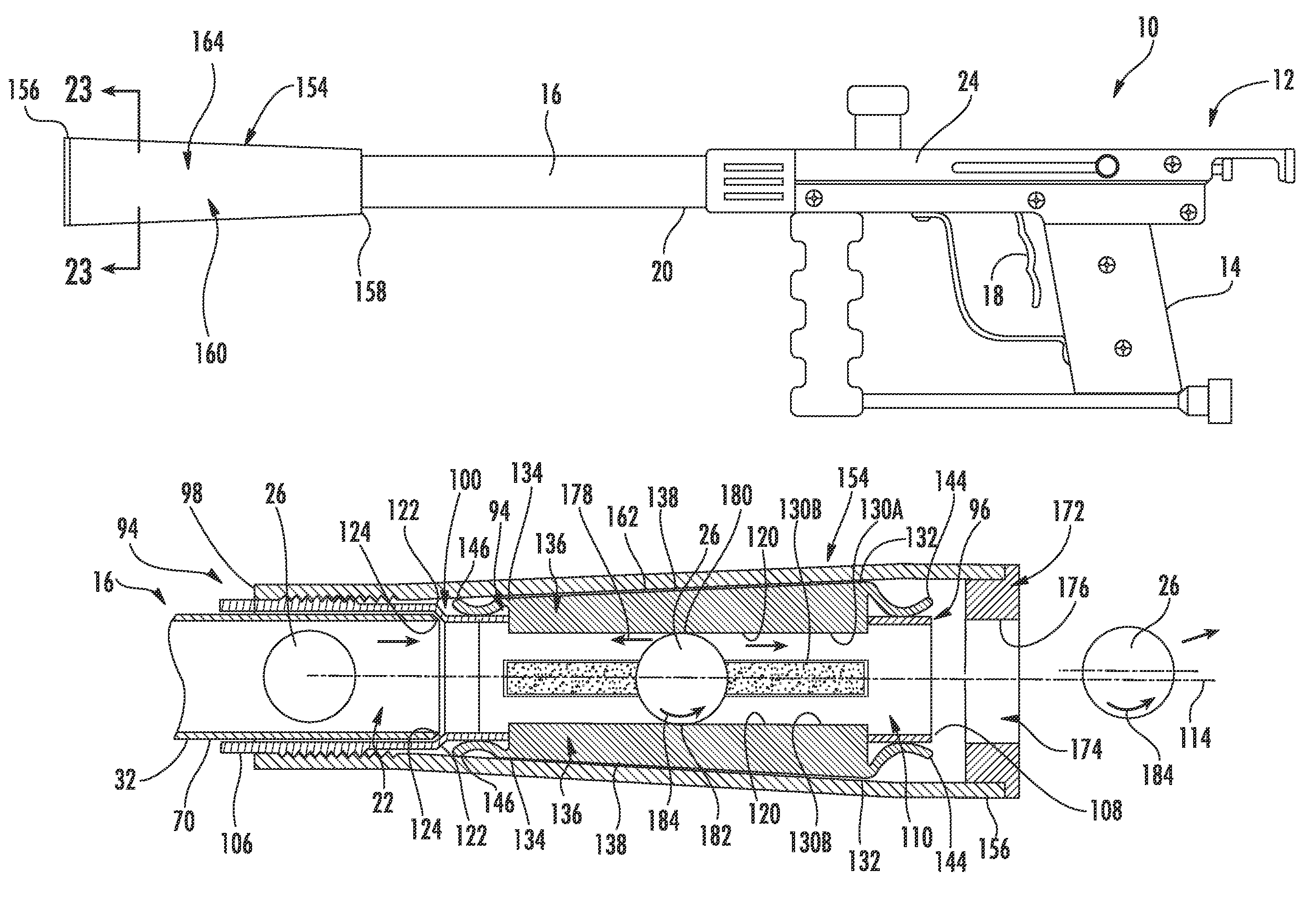
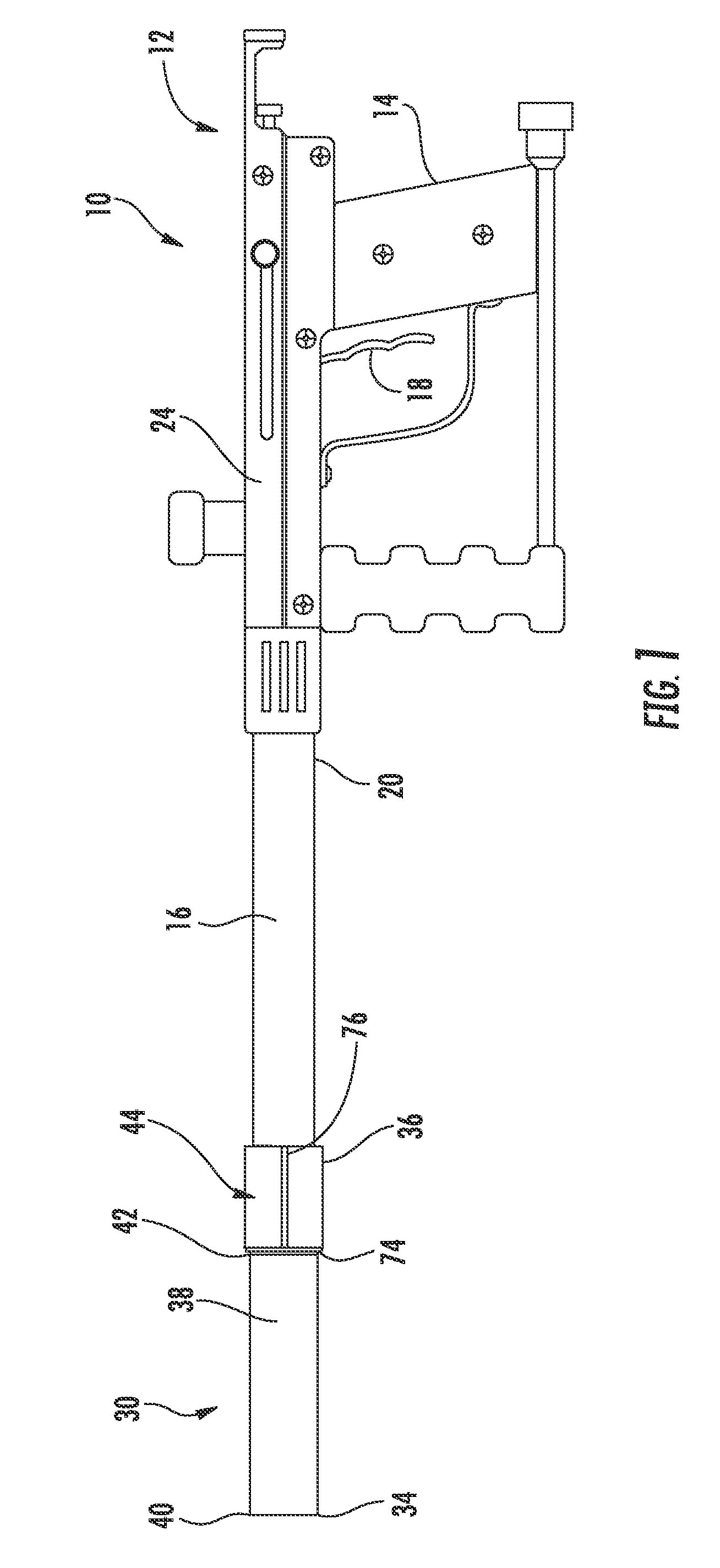
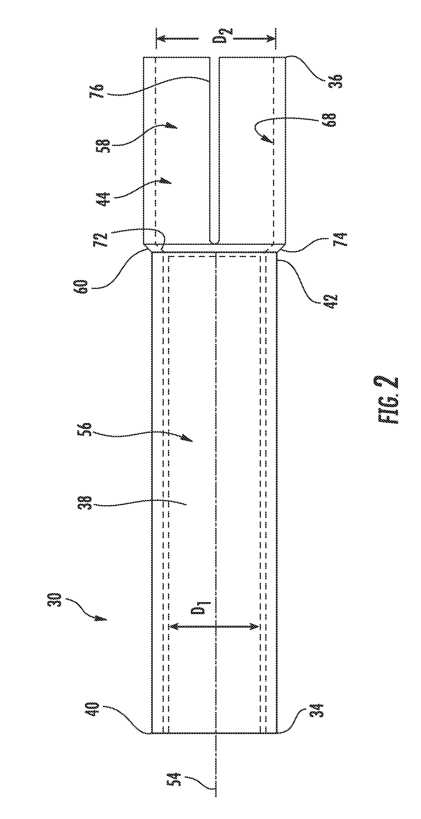
[0040]FIGS. 1-5, show the present invention. In this embodiment, the barrel attachment 30 has a first end 34, a second end 36 opposite the first end 34 and a housing. Preferably, the barrel attachment 30 is cylindrically shaped, and formed from a material such as plastic, rubber or metal.

[0041]As shown in FIGS. 1 and 2, the barrel attachment 30 has a first portion 38 having a first end 40 and a second end 42 and a sleeve portion or sleeve 44 extending adjacent the second end 42 of the first portion 38. As shown in FIG. 3, the first portion 38 includes an inner wall 46 divided into two portions designated as a first inner wall 48 that runs along half of the circumference of the inner wall 46 of the first portion 38, and a second inner wall 50 that runs along the other half of the circumference of the inner wall 46 of the first portion 38.

[0042]The walls 48 and 50 define a through passage or longitudinal projectile passage 52 that runs along a central longitudinal axis 54 (shown in FI...

second embodiment

[0052]In FIG. 7, the user 28 rotates the barrel attachment 30 left to cause left or “sidespin,” and in FIG. 8, the user 28 rotates the barrel attachment 30 right to cause a sidespin to the right. Additionally, as shown in FIG. 9 being able to fire a projectile 26 with an altered trajectory allows a user 28 to hit a target 86 behind an obstruction 88 while the user 28 stays hidden behind another obstruction 92 such as a tree and thereby avoid being detected or being the victim of return enemy fire. Note that the trajectories in FIGS. 6-9 have been exaggerated for illustrative purposes, and may not reflect actual projectile 26 trajectories or paths. Also, the barrel attachment 94 with adjustment sleeve 154 of the second embodiment can be used to produce the trajectories shown in FIGS. 6-9 and described above.

[0053]As explained in detail below, the barrel attachment 30 is rotatable three-hundred-and-sixty (360) degrees relative to the barrel 16, which allows a user 28 to selectively va...


PUM


Abstract

This invention is a barrel attachment attachable to the firing end of the barrel of a compressed gas gun and a method of using the same. The barrel attachment allows a user to spin a projectile fired from the gas gun just before it exits the barrel attachment. This spin alters the projectile's normally straight trajectory; in other words, it makes the projectile curve. The barrel attachment is adjustable. In the preferred embodiment, the user or shooter can adjust the amount of spin and thereby the amount that the projectile curves by rotating an adjustment sleeve about the barrel attachment, which causes contact pads to protrude into the passage of the barrel attachment. In the preferred embodiment, the user can adjust the direction of curve by rotating the barrel attachment about the gun barrel.

Description

CROSS REFERENCE TO RELATED APPLICATIONS[0001]This application claims the benefit of U.S. provisional patent application Nos. 60 / 695,685 and 60 / 695,732, filed on Jun. 30, 2005, the entire contents of which are incorporated by reference as if fully set forth herein.FIELD OF INVENTION[0002]The present invention relates generally, to accessories for compressed gas guns, and more specifically, to barrel attachment accessories that can affect the trajectory of a projectile fired from a compressed gas gun. A method of imparting spin on a projectile fired from a compressed gas gun is also provided.BACKGROUND[0003]Action sports such as paintball have become very popular activities. Paintball is a sporting game having two teams of players usually trying to capture one another's flag. The sport is played on a large field with opposing home bases at each end. Each team's flag is located at the player's home base. In addition, all of the players have compressed gas guns (referred to herein as ei...

Claims


Application Information

Patent Timeline
Patent Type & Authority Patents(United States)
IPC IPC(8): F41B11/00
CPCF41B11/00F41A21/32
Inventor FINSTAD, MARK T.
Owner KORE OUTDOOR US INC
Learn More