
In-vehicle input unit

a technology of input unit and input switch, which is applied in the direction of mechanical control devices, instruments, process and machine control, etc., can solve the problems of limiting the number of switches which can be provided in the steering wheel, and affecting the safety of drivers, so as to achieve the effect of preventing drivers from driving safely and without imposing a heavy burden on the eyes of drivers

Active Publication Date: 2009-10-13
PANASONIC CORP
View PDF9 Cites 13 Cited by
  • Summary
  • Abstract
  • Description
  • Claims
  • Application Information

AI Technical Summary

Benefits of technology

The present invention provides an in-vehicle input unit that allows drivers to operate switches while driving safely and without having to look away from the front visibility. The input unit includes a head-up display that displays a virtual image of a hierarchical menu on the windshield in front of the driver's seat, and a steering wheel with multiple switches that correspond one to one with the virtual selection items on the menu. The driver can easily operate the switches without having to look away from the front visibility, which reduces the burden on the driver's eyes and ensures safe driving.

Problems solved by technology

This makes it hard for the driver to manipulate the input units.
However, a limit is set to the number of switches which can be provided in the steering wheel.
This hinders the driver from driving safely.
Thereby, the driver's eyes are focused on a short-distance spot, thus imposing a burden on the eyes.
Another disadvantage also arises when the driver operates functions after selecting the equipment.
This hinders the driver from driving safely.
Thereby, from the distant spot, the driver's eyes are focused on such a short-distance spot, thus imposing a burden on the eyes.

Method used


Image

  • In-vehicle input unit
  • In-vehicle input unit
  • In-vehicle input unit

Examples


first embodiment

[0025]Hereinafter, the present invention will be described using its first embodiment.

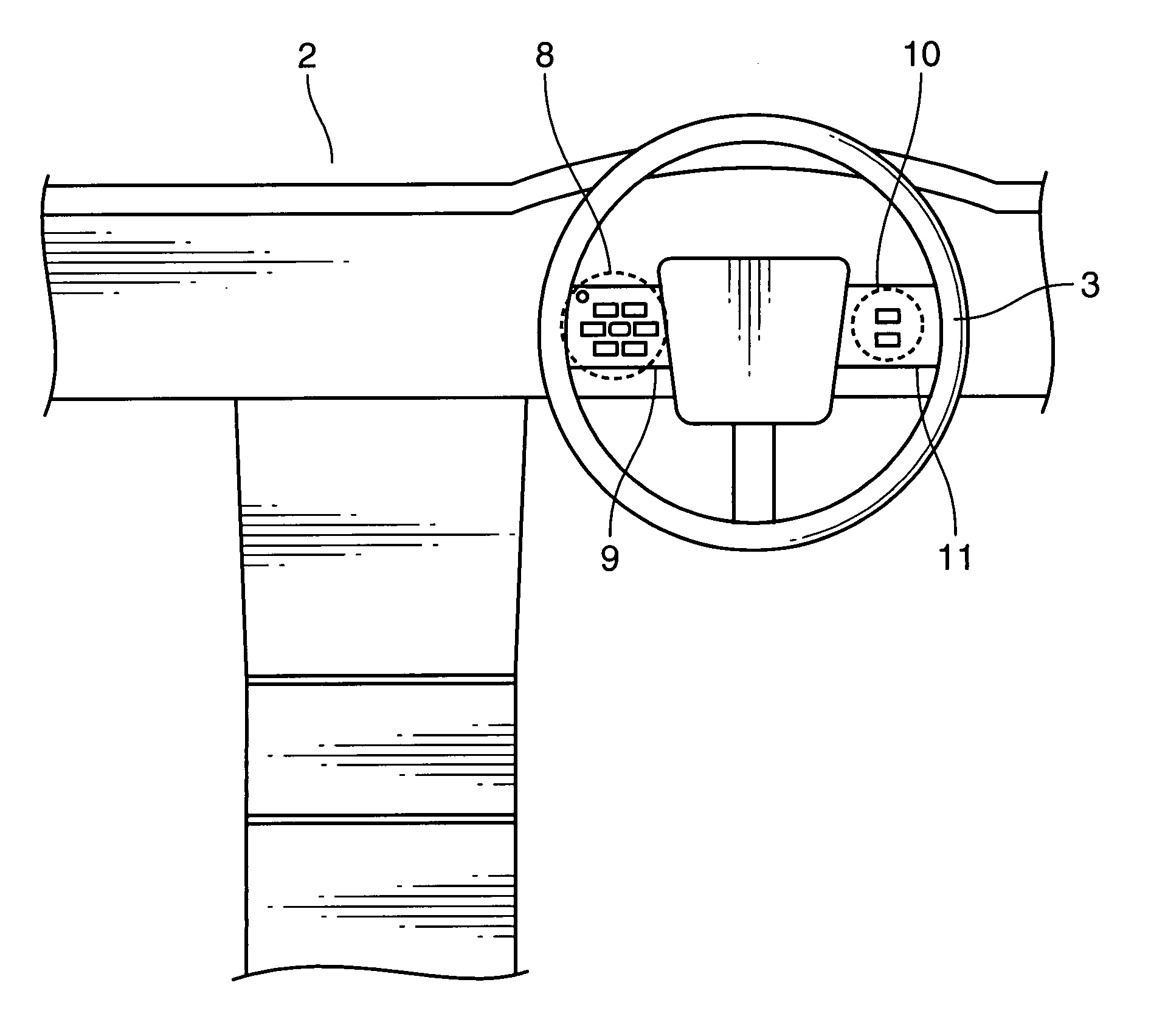
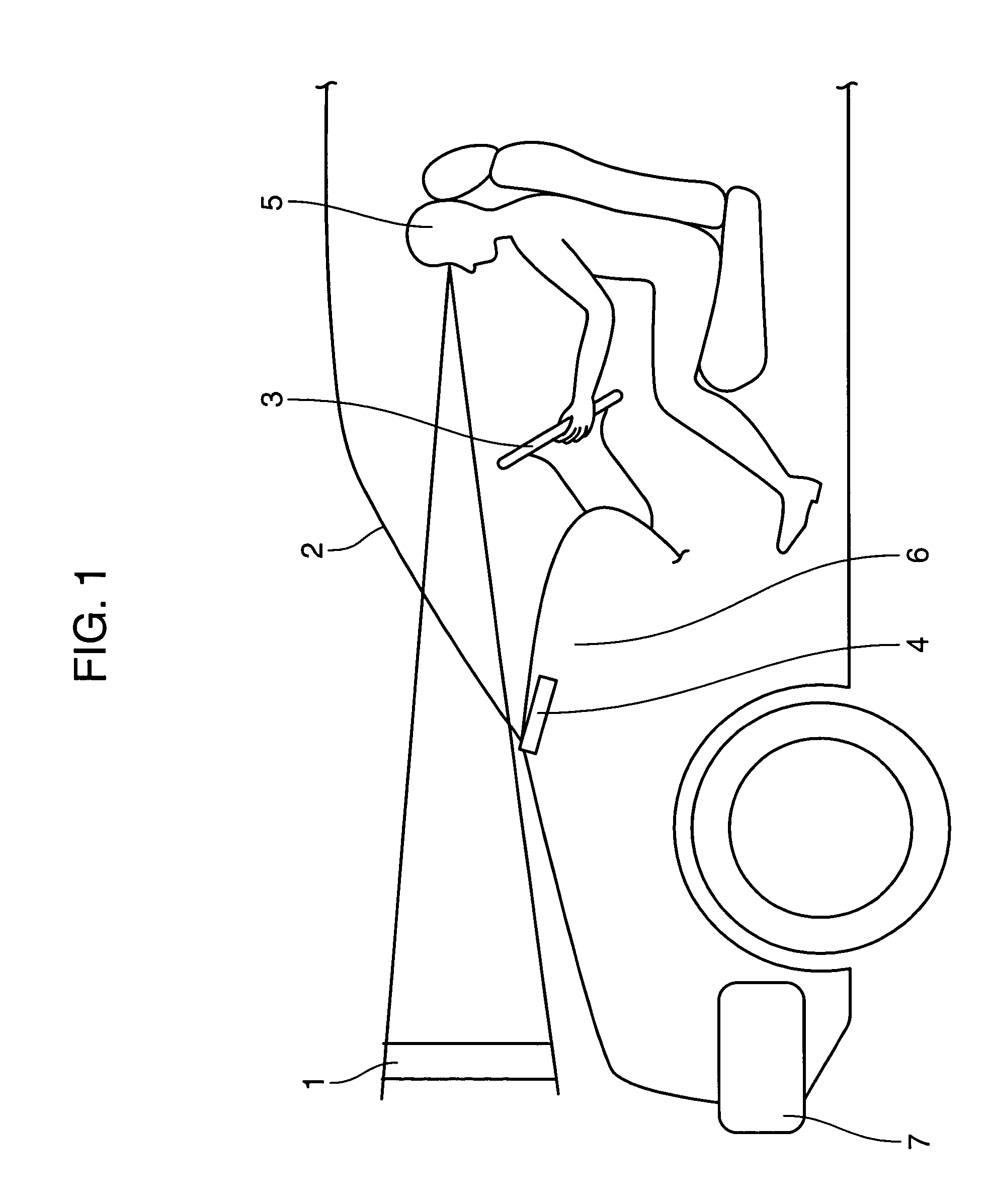
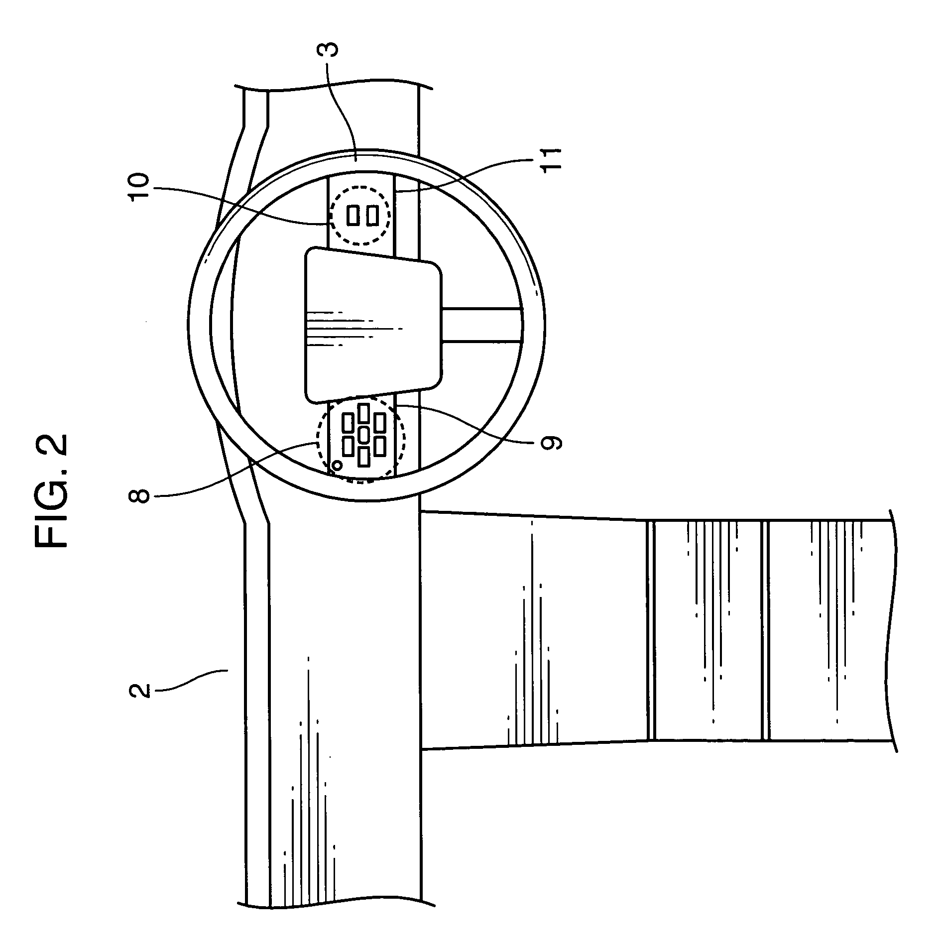
[0026]FIG. 1 is a side view showing the arrangement of a vehicle and an in-vehicle input unit according to the first embodiment of the present invention. FIG. 2 is a front view showing the arrangement as seen from the driver's seat of the in-vehicle input unit according to the first embodiment of the present invention. FIG. 3 is an enlarged perspective view of a switch portion provided in a steering spoke (i.e., the spoke) on the left side as seen from the driver's seat according to the first embodiment of the present invention. FIG. 4 is an enlarged perspective view of a switch portion provided in a steering spoke on the right side as seen from the driver's seat according to the first embodiment of the present invention. FIG. 5 is a block diagram, showing an example of the electrical configuration of the in-vehicle input unit according to the first embodiment of the present invention. FIG. 6 is a ...

second embodiment

[0048]Hereinafter, the present invention will be described using its second embodiment. FIG. 10A and FIG. 10B are each an enlarged perspective view of an example of a switch portion provided in a steering spoke on the left side if seen from a driver's seat according to the second embodiment of the present invention. FIG. 11A and FIG. 11B are each an enlarged perspective view of another example of a switch portion provided in the steering spoke on the left side if seen from the driver's seat according to the second embodiment of the present invention.

[0049]In FIG. 10A, FIG. 10B and FIG. 11A, FIG. 11B, input switches for operating the plurality of pieces of in-vehicle equipment are the left steering switch 8 and a changing switch 8a which are provided in a left steering spoke 9. The left steering switch 8 is configured so that a switch 8b, a switch 8c, a switch 8d, a switch 8f, a switch 8g, a switch 8h adjoin and surround each central switch 8i, 8j, 8k, 8l. In a position apart from th...


PUM


Abstract

An in-vehicle input unit is provided which includes: a head-up display which projects a hierarchical menu for operating a plurality of pieces of in-vehicle equipment onto a windshield in front of a driver's seat, and displays the hierarchical menu as a virtual image ahead of the windshield; and a plurality of switches which are disposed in a steering wheel so that several switches adjoin and surround one central switch, in which the head-up display displays selection items on the hierarchical menu as the virtual image so that the selection items correspond one to one to the plurality of switches disposed in the steering wheel.

Description

BACKGROUND OF THE INVENTION[0001]1. Field of the Invention[0002]The present invention relates to an in-vehicle input unit which is capable of operating a hierarchical menu for operating a plurality of pieces of in-vehicle equipment, using switches provided in a steering wheel, while viewing its image displayed by a vehicle display unit.[0003]2. Description of the Background Art[0004]In recent years, an automobile has more and more equipment on board so that safety and comfort can be improved. Specifically, an air conditioner or an audio system is provided as standard equipment, and a car-navigation system has been popular. In the years ahead, equipment related to car communication mainly including telematics, or a driving support device for adaptive cruise control system, lane keeping support system, blind spot monitoring system or the like, spreading from a luxury car to a popular car, is expected to be increasingly popular.[0005]Conventionally, for example, in-vehicle equipment, s...

Claims


Application Information

Patent Timeline
Patent Type & Authority Patents(United States)
IPC IPC(8): G05G1/02G05G1/08B60K35/10G05G1/01
CPCB60K37/06G02B27/01B60K2350/928B60K35/10B60K35/60B60K2360/782B60K35/22
Inventor TANAKA, TSUYOSHIISHIAI, YASUSHI
Owner PANASONIC CORP
Learn More