
Method of making orthopedic implants and the orthopedic implants

a technology of orthopedic implants and implants, applied in the field of making orthopedic implants and orthopedic implants, can solve the problems of less success, less success, and difficulty in reconstruction

Inactive Publication Date: 2009-10-13
ORTHOHELIX SURGICAL DESIGNS
View PDF8 Cites 227 Cited by
  • Summary
  • Abstract
  • Description
  • Claims
  • Application Information

AI Technical Summary

Benefits of technology

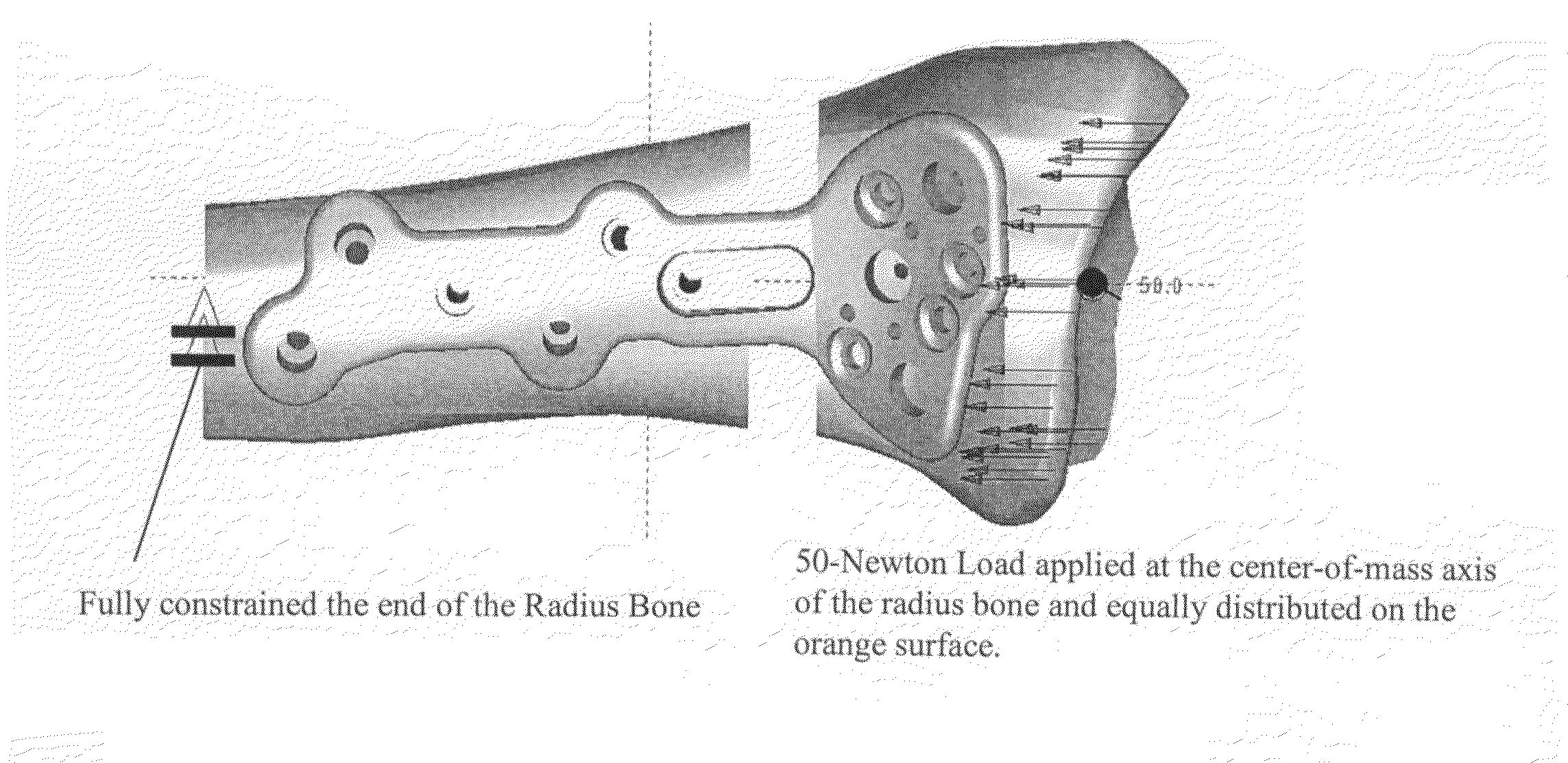
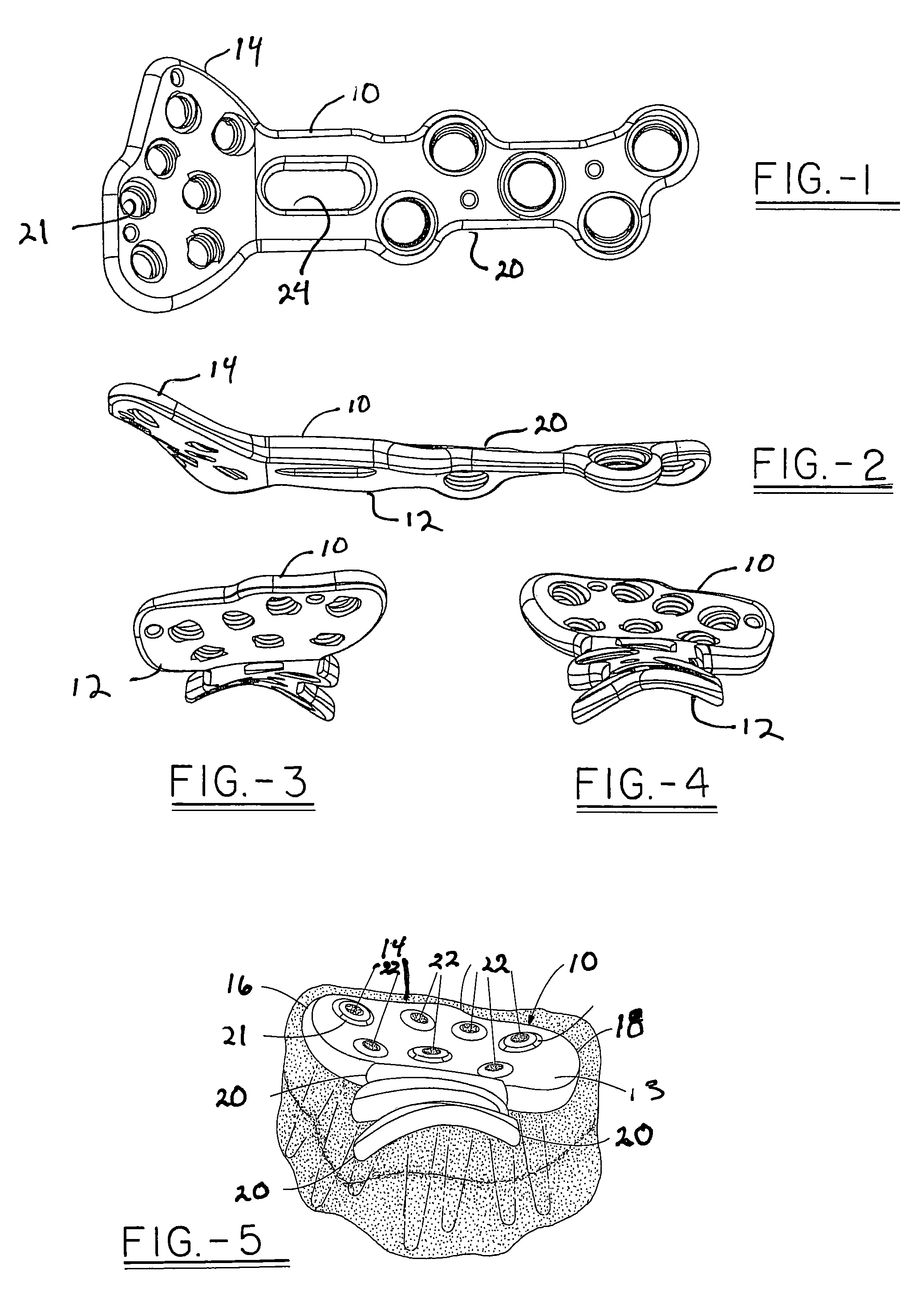
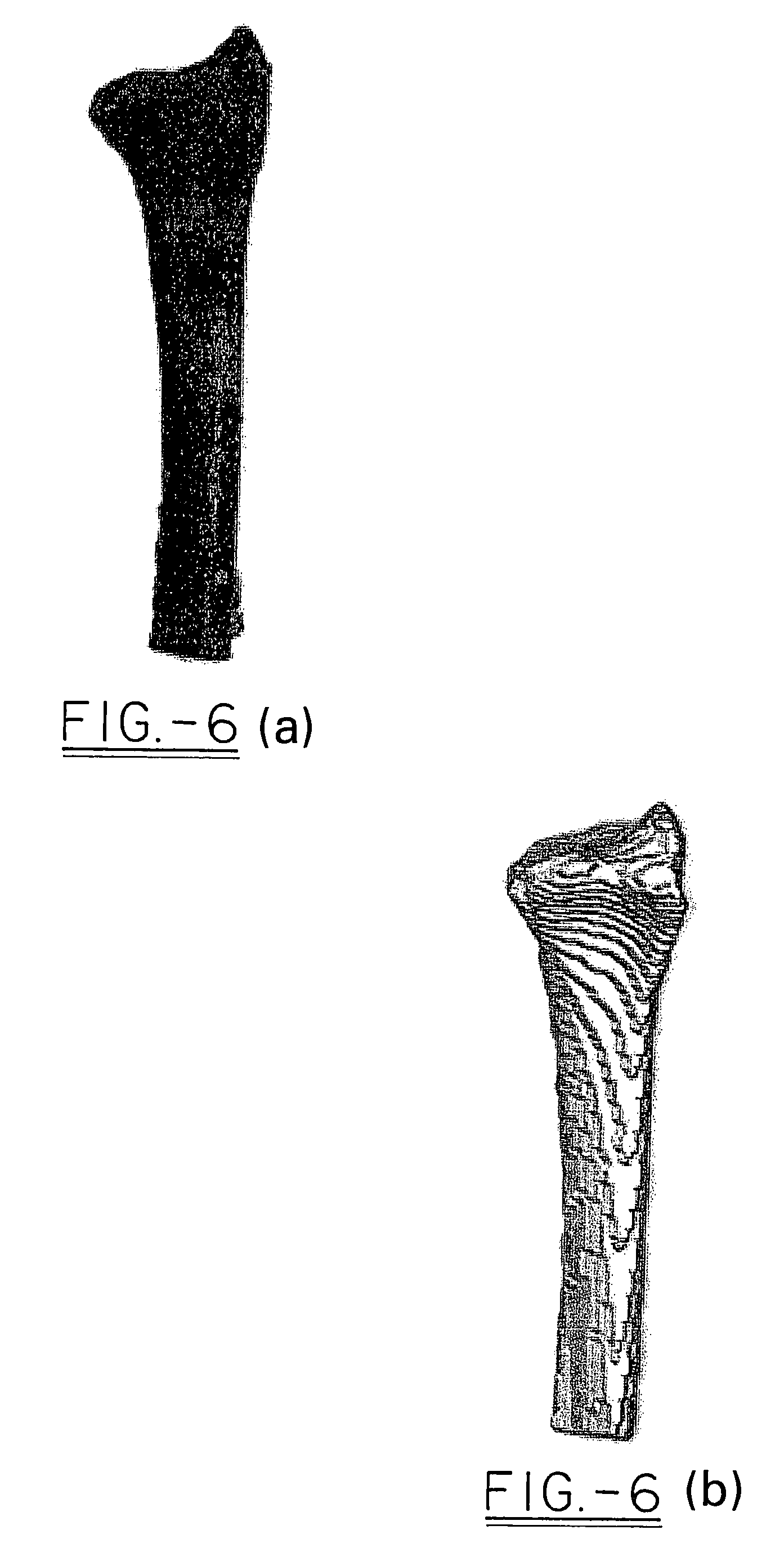
"The invention is a method for collecting and analyzing digital information about a sample population for a particular anatomical site. This information can be generated from known imaging techniques and can include samples from cadavers or live specimens. The samples are harvested from a group of individuals with specific characteristics, such as age and size. The bone samples are then cleaned, disarticulated, and transected. High resolution CT scans are taken of the bone and compared with the CT scans and caliper measurements. The resulting images are saved and used to create solid models of the bone. These models are then aligned and overlaid to create a composite model. Plastic prototypes are made from the composite model and fitted to the bone models for further adjustments. The final design takes into account the indication and surgery and is ready for use."

Problems solved by technology

This paradigm presents several problems for the attending surgeon.
First, the surfaces of bone are far from flat, and the smaller the bone, the greater the relative contouring that the surgeon had to accomplish during the surgery.
Second, while intact cadaveric bone can provide a basis for contouring a flexible plate, this idea is less successful with bone that has been fragmented, and the worse the break, the more difficult the reconstruction.
However, while several authors have utilized CT of the distal radius for specific diagnoses, no high-resolution model of the distal radius articular surface, epiphysis, and metaphysis based on data acquired from human materials has been reported in the literature.

Method used


Image

  • Method of making orthopedic implants and the orthopedic implants
  • Method of making orthopedic implants and the orthopedic implants
  • Method of making orthopedic implants and the orthopedic implants

Examples


Embodiment Construction

[0022]In order to begin the design process of the present invention, digital information is collected for a particular anatomical site. The information can be generated from known imaging techniques including CT scans, MRI or radiographic techniques. The sample may include cadavers or live specimens. The sample group may be defined to include particular characteristics, for example, a geriatric or pediatric population, or a generalized sample of the relevant population for a location. In particular, a representative sample of from about 4 to about 50, and more preferably from about 6 to about 30 and most preferably from about 10 to about 20 samples are collected. In this instance, a sample of sixteen right distal radius specimens were harvested from preserved cadavers at Washington University School of Medicine. Six male cadavers and 10 female cadavers were used, ranging in age at time of death from 61 to 98 (Table 1). All soft tissue was stripped from the bone samples beginning at ...


PUM


Abstract

The present invention relates to a method of designing an orthopedic implant in which a plurality of samples of the bone are selected and a CT scan of each of the samples of the bone is taken so that the data from the CT scan can be used to generate a 3D graphical solid body model of each of the sample of the bone. The 3D graphical models are placed into a category of one or more of average, small, and large, and the center of mass and an X, Y and Z plane for each model is determined. The 3D graphical models for one category is assembled and aligned at the center of mass to create a categorized composite 3D graphical solid body model of the bone. The categorized composite 3D graphical model is sectioned at a specified interval to create a lofted contoured surface of a selected thickness which is cut to create a categorized implant profile. The categorized implant profile is graphically fit on the categorized composite 3D graphical model and on the 3D graphical model of each of the sample of the bone in a category to check for conformity to the surface of the bone. The categorized implant profile is used to create a design of the implant.

Description

FIELD OF THE INVENTION[0001]The invention relates to a method of designing site specific orthopedic plates, and more particularly to a method of designing an orthopedic plate that mimics the topography of a bone site and which is intended for fixation to a specific part of anatomy for stabilization of a characteristic type of fracture or osteotomy.BACKGROUND OF THE INVENTION[0002]The paradigm for prior art orthopedic plates has involved drawing an image of the plate to suit a general outline of a site where the plate was intended to be implanted. Thus, the plate began its conception as a two dimensional representation. The final manifestation was crafted from metal and often had no, or very crude profiling in the Z direction. As this corresponded poorly with the surface of the bone that it was designed to fit, the plate was made relatively thin to allow the surgeon to contour the plate before implantation. In addition, the plate was made somewhat thin so that it could be fixed in pl...

Claims


Application Information

Patent Timeline
Patent Type & Authority Patents(United States)
IPC IPC(8): G06F19/00A61F2/28
CPCA61B17/8061G06F19/3437A61B2017/00526Y10S623/901G16H50/50B33Y80/00
Inventor MARTIN, AMANDADUCHARME, DUSTINSTRNAD, LEE A.
Owner ORTHOHELIX SURGICAL DESIGNS
Learn More