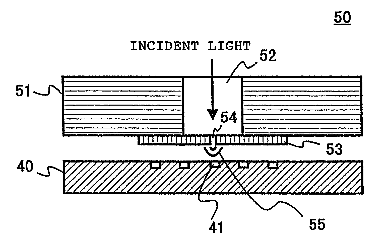
Near-field optical probe for reproducing information on a recording medium using near-field light
a near-field light and optical probe technology, applied in nanoinformatics, instruments, record information storage, etc., can solve the problems of difficult near-field optical, inability to achieve high resolution observation, and density of information recording that cannot be achieved by conventional optical microscopes
- Summary
- Abstract
- Description
- Claims
- Application Information
AI Technical Summary
Benefits of technology
Problems solved by technology
Method used
Image
Examples
embodiment 1
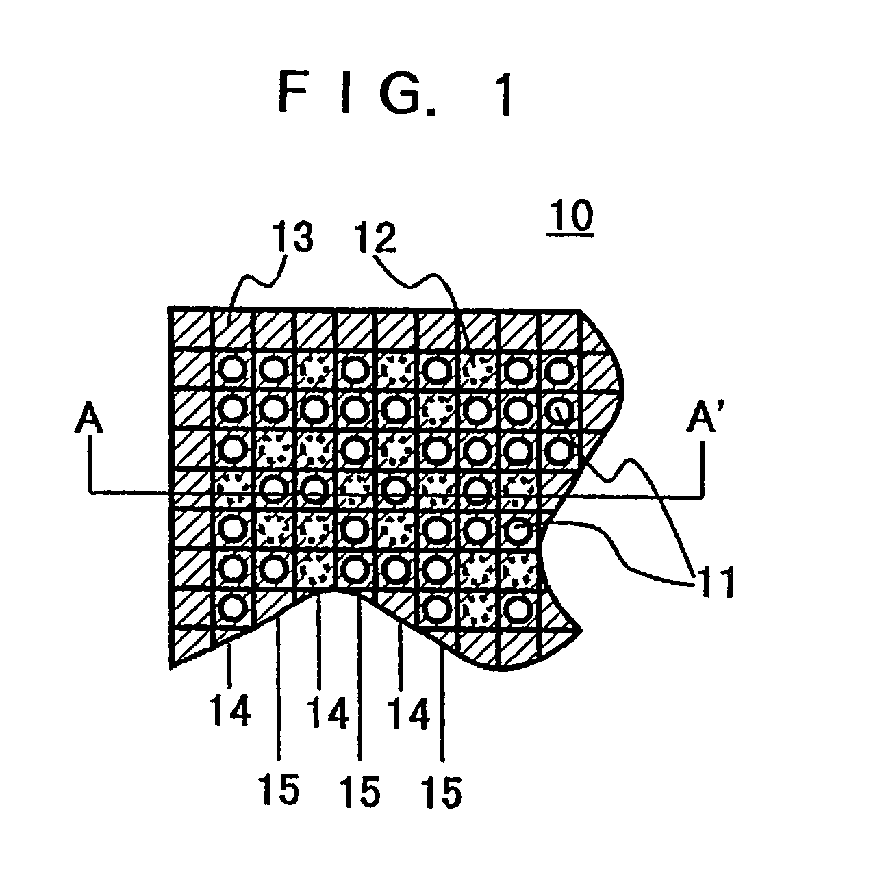
[0042]Referring to FIG. 1, there is illustrated one part of a recording medium according to Embodiment 1 of the present invention. A recording medium 10 in the figure includes a substrate having a sufficient transmittance of light to produce near-field light, on which is formed a phase shifter arrangement layer. Furthermore, a data mark arrangement layer is formed on the phase shifter arrangement layer. Herein, the data mark arrangement layer is a region to be formed with a data mark.
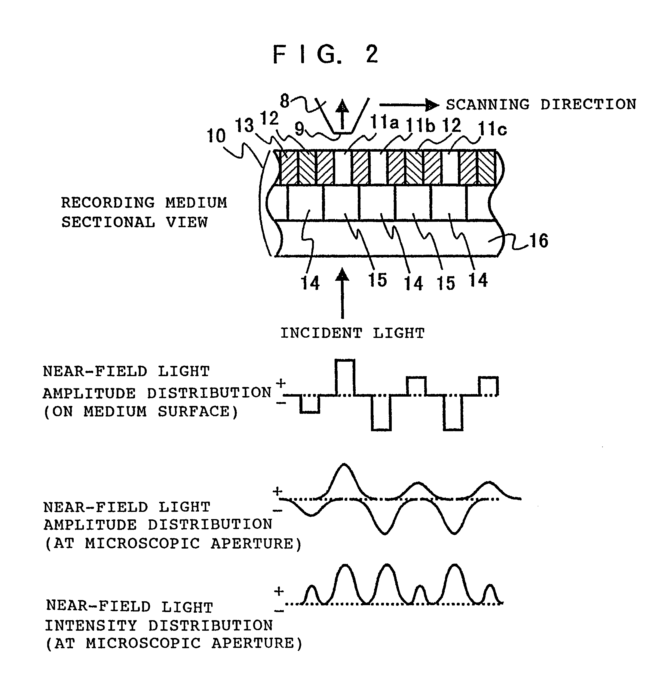
[0043]In FIG. 1, the recording medium 10 has a data mark arrangement layer to be formed with data marks 11 serving as the light transmittance regions to produce comparatively intense near-field light, for example. The proper arrangement of data marks 11 makes it possible to achieve information recording. Note that in the figure the circle 12 depicted by a dotted line represents a position at which a data mark may be provided. It is assumed herein that the data mark 11 corresponds to information of a log...
embodiment 2
[0054]Explanations will be now made on a recording medium according to Embodiment 2. FIG. 3 shows one part of the recording medium of Embodiment 2. The recording medium 20 of FIG. 3 is different from the recording medium 10 according to Embodiment 1 only in that no shade film is coated over a surface of the recording medium. Accordingly, the recording medium 20 of FIG. 3 is structured by a phase shifter arrangement layer formed on a base member having a sufficient transmittance for producing near-field light, and a data mark arrangement layer formed on the phase shifter arrangement layer.
[0055]Here, the phase shifter arrangement layer is formed alternately with a phase shifter regions 24 and transmission regions 25 similarly to Embodiment 1 while the data mark arrangement layer is a region where data marks 21 are to be formed. Note that circles 22 shown by dotted lines in the figure represent positions that data marks are possible to provide.
[0056]Meanwhile, in FIG. 1 the shade film...
embodiment 3
[0064]Explanations will now be made on a recording medium according to Embodiment 3. FIG. 5 shows one part of the recording medium of Embodiment 3. The recording medium 30 of FIG. 5 has a phase shifter 33 coated on a base member having a sufficient transmittance for producing near-field light, and data marks 31 provided in areas not coated with the phase shifter 33 thus storing information. Note that circles 32 shown by dotted lines represent positions that data marks are possible to provide. Here, the phase shifter 33 has a transmittance of approximately 2-20% for a wavelength of an oozing portion of the incident light illuminated at the backside of the recording medium 30 under a condition of total reflection. The phase shifter is also formed of a translucent material having a phase difference of 180 degrees with respect to the base member 36 of the recording medium 30 (particularly, the translucent phase shifter is referred to as a half-tone type phase shifter), e.g., an applied ...
PUM
| Property | Measurement | Unit |
|---|---|---|
| transmittance | aaaaa | aaaaa |
| wavelength | aaaaa | aaaaa |
| transmittance | aaaaa | aaaaa |
Abstract
Description
Claims
Application Information
 - R&D
- Intellectual Property
- Life Sciences
- Materials
- Tech Scout
- Unparalleled Data Quality
- Higher Quality Content
- 60% Fewer Hallucinations
Browse by: Latest US Patents, China's latest patents, Technical Efficacy Thesaurus, Application Domain, Technology Topic, Popular Technical Reports.
© 2025 PatSnap. All rights reserved.Legal|Privacy policy|Modern Slavery Act Transparency Statement|Sitemap|About US| Contact US: help@patsnap.com


