
Ion exchanger container for a motor vehicle

a technology of ion exchanger and motor vehicle, which is applied in the direction of ion exchange water treatment, machine/engine, water/sewage treatment, etc., and can solve problems such as the risk of aqueous solution freezing

Active Publication Date: 2009-10-13
MANN HUMMEL GMBH
View PDF12 Cites 1 Cited by
  • Summary
  • Abstract
  • Description
  • Claims
  • Application Information

AI Technical Summary

Benefits of technology

[0004]The object of the invention is to provide an ion exchanger vessel, particularly for use in a motor vehicle, in which damage to components at low temperatures is prevented by simple measures. This is to be accomplished, in particular, without any additional expenditure of energy.
[0009]Preferably, at least two housings are provided for the ion exchanger vessel, such that the outer housing encloses an inner housing which contains the ion exchange material. The liquid is passed through the inner housing containing the ion exchange material, and the heating medium is conducted between the inner housing and the outer housing. In particular, the heating medium may be conducted through a helical heating line, which runs along the outside of the inner housing, i.e., between the inner and the outer housing. This embodiment has the advantage that the two liquids will not be mixed even if a component fails. Rather, the liquid flowing through the ion exchange material remains separate from the heating medium even if a component is defective.
[0010]In another advantageous embodiment, an additional housing is provided, which is an intermediate housing disposed between the inner housing and the outer housing. This creates two gaps that are separated from each other, one between the inner housing and the intermediate housing and another between the intermediate housing and the outer housing. The liquid is advantageously introduced into the ion exchanger vessel through the inner gap. The heating medium, on the other hand, is conducted through the outer gap. Both liquids flow parallel over a large area, which enhances the heat transfer from the heating medium in the direction of the liquid to be passed through the ion exchange material.
[0011]Another advantageous embodiment provides for a deformable expansion element to be disposed in the housing adjacent the flow path of the liquid. This expansion element is, in particular, elastically deformable and compensates the increased volume of the water content in the liquid if the liquid freezes. The expansion element yields under the pressure of the freezing and expanding liquid, so that the volume available in the flow path of the liquid is increased. Because of the deformation of the expansion element, the high forces occurring during the freezing process cannot destroy the ion exchanger vessel or parts thereof.
[0013]The ion exchange material is advantageously axially bounded inside the housing by a displaceable boundary disk. This displaceable boundary disk is also capable of compensating the volume when the liquid to be passed through the ion exchanger material freezes.

Problems solved by technology

Because of the relatively high water content in the urea solution (the water content is approximately two-thirds), the problem is encountered that the freezing point of the solution is higher than the temperatures occurring during a hard frost, so that there is a risk that the aqueous solution will freeze.

Method used


Image

  • Ion exchanger container for a motor vehicle
  • Ion exchanger container for a motor vehicle
  • Ion exchanger container for a motor vehicle

Examples


Embodiment Construction

[0020]In the figures, like components are identified by the same reference numerals.

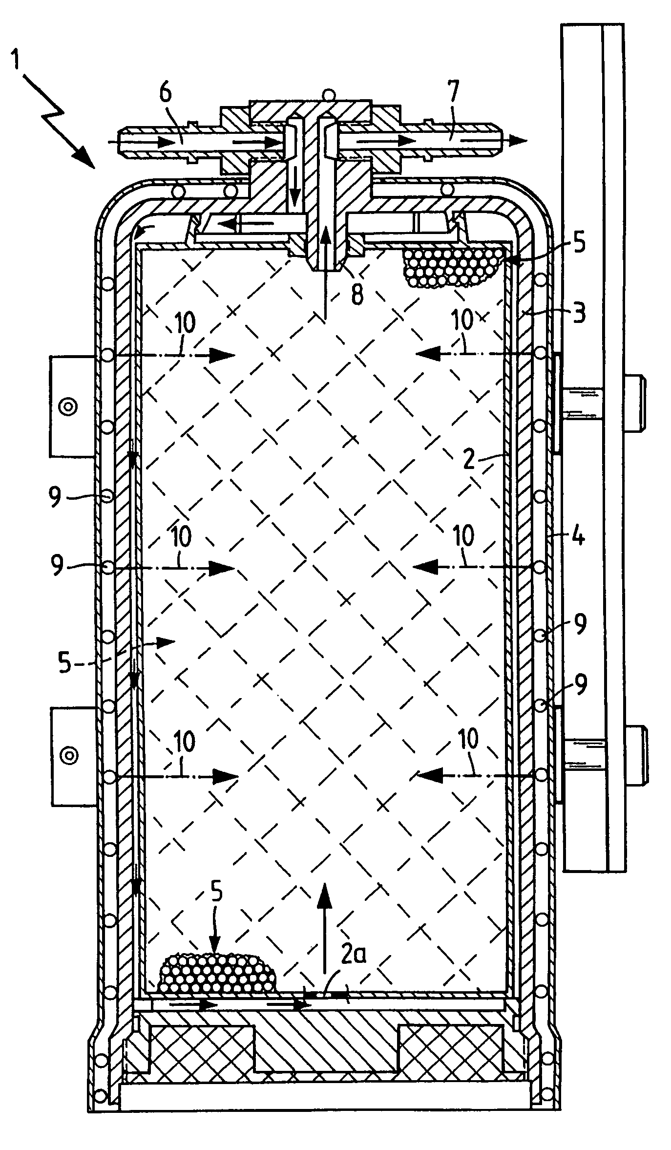
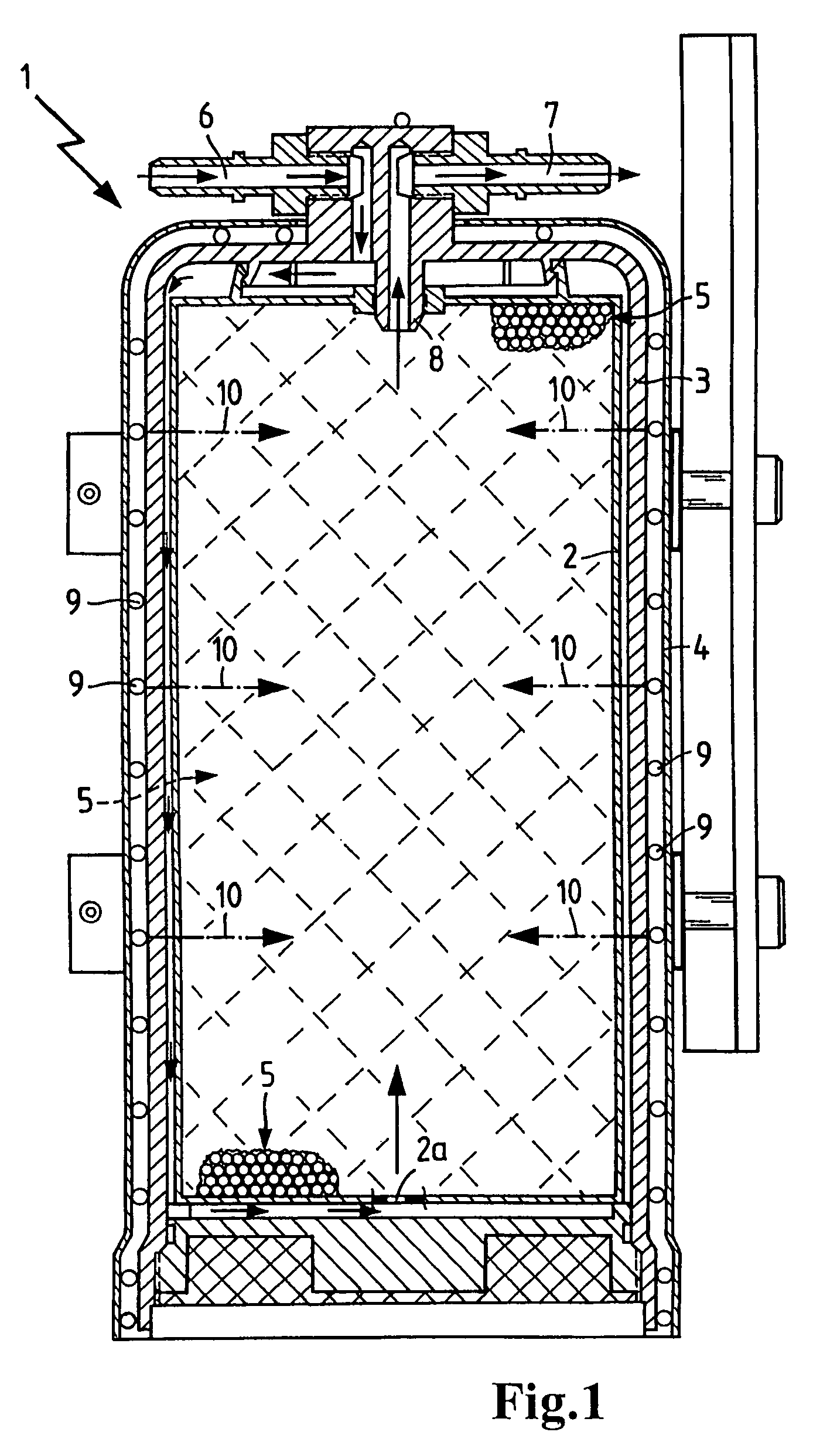
[0021]The ion exchanger vessel 1 depicted in FIG. 1 is intended for use in a motor vehicle. An aqueous urea solution, which is injected into the exhaust stream for oxygen reduction of nitrogen oxides, is first passed through the ion exchanger vessel to decalcify the water content in the aqueous urea solution. In the ion exchanger, calcium ions contained in the water content are exchanged for sodium ions. This decalcifies the water and prevents calcium deposits on the components that come into contact with the aqueous urea solution.

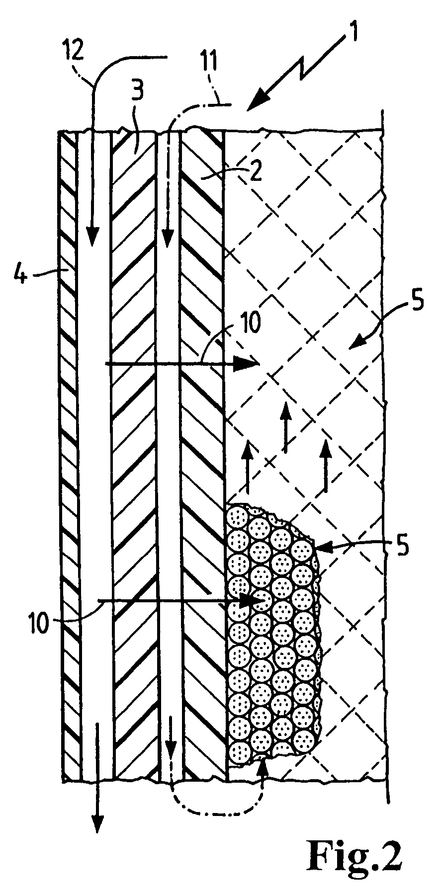
[0022]The ion exchanger vessel 1 comprises three nested housings 2, 3 and 4, such that the inner housing 2 receives the ion exchange material 5, through which the aqueous urea solution is to pass. The aqueous urea solution is fed into the ion exchanger vessel 1 through an inlet line 6 and, after flowing through the ion exchange material 5 in the inner housing 2, flows out t...


PUM

PropertyMeasurementUnit
freezing pointaaaaaaaaaa
temperaturesaaaaaaaaaa
energyaaaaaaaaaa

Abstract

An ion exchanger vessel having a housing for receiving an ion exchange material and an inlet line and a discharge line in the housing for feeding and discharging a liquid to be passed through the ion exchange material. To heat the liquid, a heating medium is guided through the ion exchanger vessel, such that the heating medium is separated from the liquid to be passed through the ion exchange material.

Description

BACKGROUND OF THE INVENTION[0001]The present invention relates to an ion exchanger vessel, particularly for use in a motor vehicle, having a housing for receiving an ion exchange material and an inlet line and discharge line in the housing for introducing and discharging a liquid to be passed through the ion exchange material.[0002]Ion exchanger vessels of this type are used, for instance, in the exhaust tract of motor vehicles having an internal combustion engine to remove calcium ions from the water content in an aqueous urea solution. This prevents calcium deposits in injection nozzles used to inject the aqueous urea solution into the exhaust stream for oxygen reduction of nitrogen oxides. The ion exchanger decalcifies the water content in the urea solution to increase the life of the components coming into contact with the urea solution.[0003]Because of the relatively high water content in the urea solution (the water content is approximately two-thirds), the problem is encounte...

Claims


Application Information

Patent Timeline
Patent Type & Authority Patents(United States)
IPC IPC(8): B01D35/18
CPCB01D53/92B01J47/002B01J47/06F01N3/2066Y02T10/24F01N2610/02F01N2610/10F01P2060/00B01J47/012C02F1/42C02F2103/023Y02A50/20Y02T10/12
Inventor AMESOEDER, DIETERSCHRECKENBERGER, DIETER
Owner MANN HUMMEL GMBH
Learn More