
Method and apparatus for bilateral high pass filter

a filter and high-pass technology, applied in the field of filtering of digitally represented images, can solve the problems of slow spatial variation, degraded image quality, and increased noise level of captured images, no matter how small

Active Publication Date: 2009-10-06
ATI TECH INC
View PDF10 Cites 40 Cited by
  • Summary
  • Abstract
  • Description
  • Claims
  • Application Information

AI Technical Summary

Problems solved by technology

When an image is digitally captured, an inevitable consequence of the capture process is the addition of random “noise” that degrades, no matter how slightly, the quality of the captured image.
However, the assumption of slow spatial variations fails at edges (i.e., boundaries between regions of substantially different colors within the image), which are consequently blurred by low-pass filtering.
However, such camera systems often suffer from relatively low quality optics and light sensing components, which subsequently tend to increase the noise level in captured images.

Method used


Image

  • Method and apparatus for bilateral high pass filter
  • Method and apparatus for bilateral high pass filter
  • Method and apparatus for bilateral high pass filter

Examples


Embodiment Construction

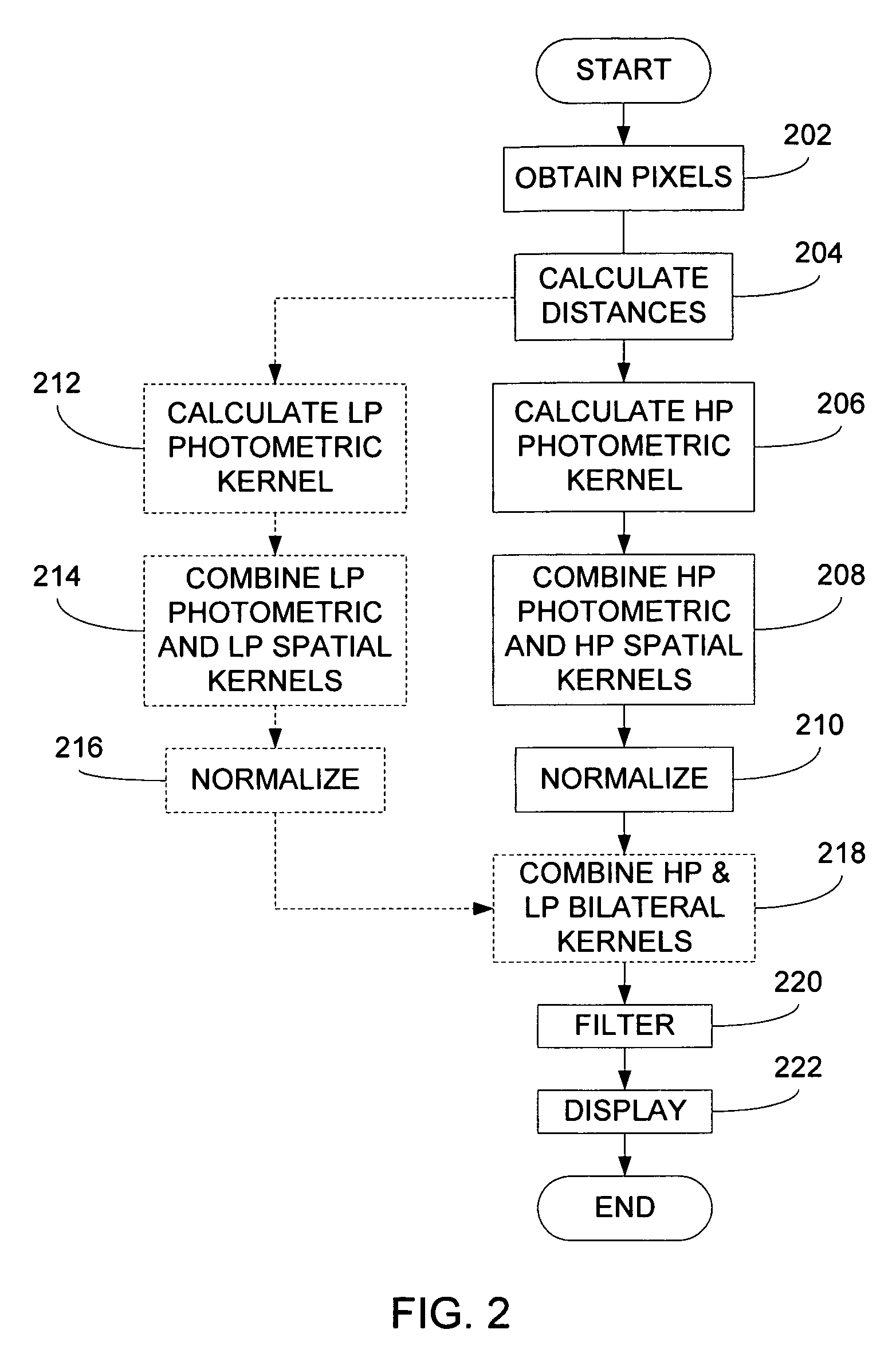
[0014]Briefly, an embodiment of the present invention provides a method for filtering at least one pixel of an image using a bilateral high pass filter and, optionally, a bilateral low pass filter. In particular, a target pixel and surrounding pixels corresponding to the target pixel are obtained from a digitally represented image. A bilateral high pass filtering kernel is determined based at least in part upon the target pixel and the surrounding pixels. According to one aspect of the present invention, distances, such as Euclidean distances, between the target pixel and at least some of the surrounding pixels are determined and used to calculate the bilateral high pass filtering kernel. Furthermore, in accordance with a presently preferred embodiment, a thresholding operation is performed on each of the Euclidean distances. Only those Euclidean distances comparing favorably with the threshold value give rise to a non-zero coefficient value. Thereafter, the coefficients determined ...


PUM


Abstract

A target pixel and surrounding pixels corresponding to the target pixel are obtained from a digitally represented image. A bilateral high pass filtering kernel is determined based at least in part upon the target pixel and the surrounding pixels. A high pass spatial filtering kernel is provided and multiplied with the high pass photometric filtering kernel to provide a bilateral high pass filtering kernel. The resulting bilateral high pass filtering kernel is thereafter applied to the target pixel and the surrounding pixels to provide a filtered pixel. When it is desirable to combine noise filtering capabilities with sharpening capabilities, the bilateral high pass filter of the present invention may be combined with a bilateral low pass filtering kernel to provide a combined noise reduction and edge sharpening filter. The present invention may be advantageously applied to a variety of devices, including cellular telephones that employ image sensing technology.

Description

FIELD OF THE INVENTION[0001]The invention relates generally to filtering of digitally represented images and, in particular, to devices and methods that employ bilateral filters to process digital images.BACKGROUND OF THE INVENTION[0002]Devices are known, such as laptop computers, desktop computers, cell phones, cable set top boxes, printers and other devices, that employ graphics processing that may be used to perform filtering operations on digital representations of images. Software programs for performing such filtering are also well known. A typical filtering operation performed on images is noise reduction. When an image is digitally captured, an inevitable consequence of the capture process is the addition of random “noise” that degrades, no matter how slightly, the quality of the captured image.[0003]In the broadest sense of the term “filtering,” the value of the filtered image at a given location is a function of the values of the input image in a relatively small neighborh...

Claims


Application Information

Patent Timeline
Patent Type & Authority Patents(United States)
IPC IPC(8): G06K9/40G06K9/64G06V10/30
CPCG06K9/40G06T5/20G06T5/003G06T5/002G06T2207/20192G06T2207/20028G06V10/30
Inventor SMIRNOV, MAXIMALEKSIC, MILIVOJEGOMA, SERGIU
Owner ATI TECH INC
Learn More