
Electrical distribution panel including first non-critical load bus and second critical load bus

Active Publication Date: 2009-10-06
EATON INTELLIGENT POWER LIMITED
View PDF24 Cites 40 Cited by
  • Summary
  • Abstract
  • Description
  • Claims
  • Application Information

AI Technical Summary

Benefits of technology

[0015]There is further a need for such reconfigurable electrical distribution panels that do not require unnecessary costs or components when initially configured for operation from a single power source or when reconfigured to also provide operation from a second power source.

Problems solved by technology

Unfortunately, relatively larger electric generators present various disadvantages over relatively smaller electric generators.
While smaller electric generators are typically air cooled, larger electric generators typically require a liquid cooling system with a circulation pump and radiator, thereby adding to both the costs and complexities of operating and maintaining a larger generator in comparison to a smaller generator.
Larger generators also require relatively larger quantities of maintenance fluids, including lubrication oil and coolant liquid.
However, it requires significant time and effort to rewire a load center in order to electrically connect a backup power source, such as an electric generator or other auxiliary power unit (APU) (e.g., a device whose purpose is to provide electrical energy), to critical circuits in, for example, residential and relatively smaller scale commercial structures.

Method used


Image

  • Electrical distribution panel including first non-critical load bus and second critical load bus
  • Electrical distribution panel including first non-critical load bus and second critical load bus
  • Electrical distribution panel including first non-critical load bus and second critical load bus

Examples


example 1

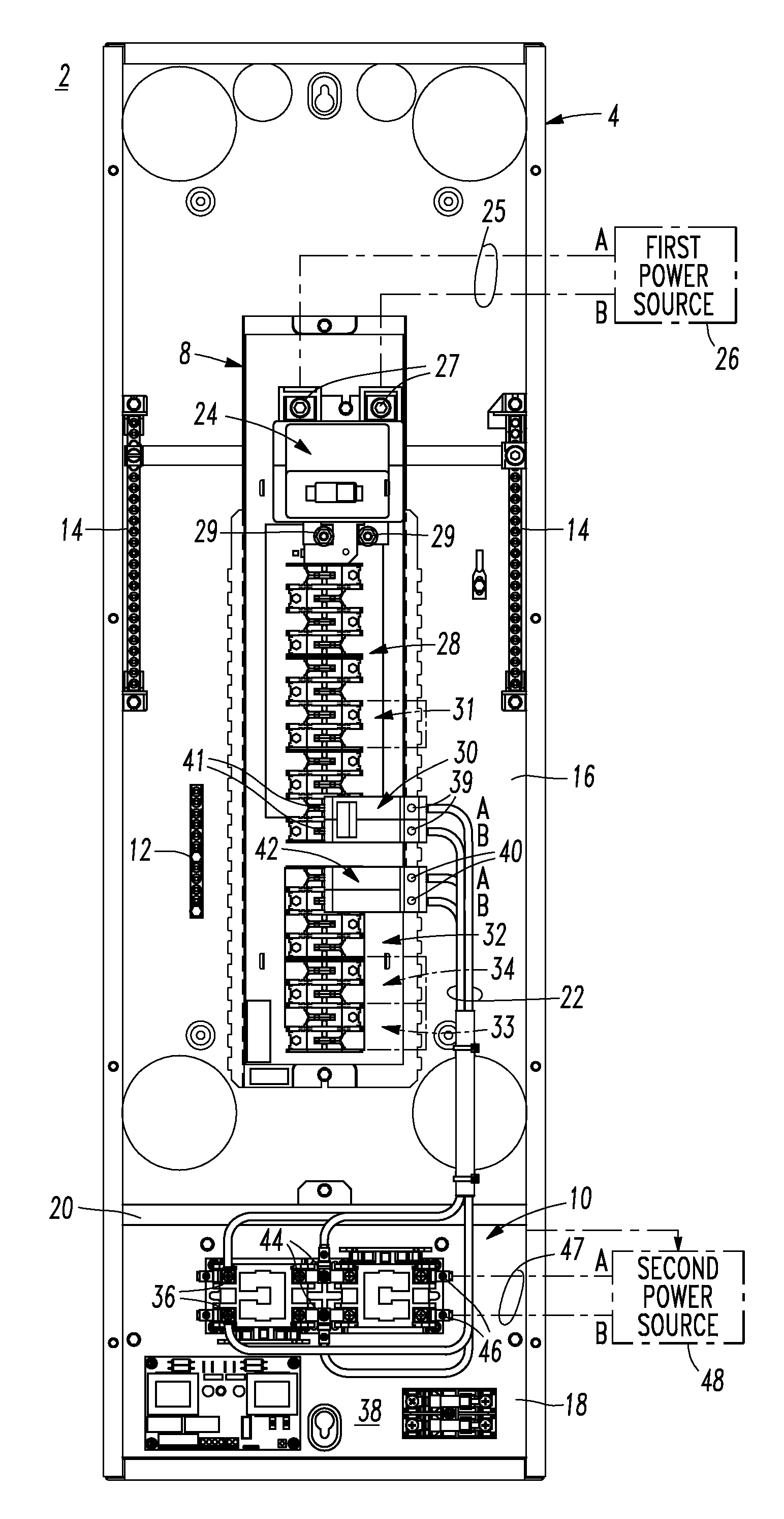
[0047]Although an example 50A version of the critical circuits of the ATS load center 202 is disclosed, a wide range of other current ratings can be provided. The branch mounted circuit breaker 30 can be a plug-on, two pole, 50 A, 240 V circuit breaker. This circuit breaker 30, when closed, supplies the second bus 32 of the load center 202 with first power from the first power source 26 (as shown in FIG. 1) under normal operation. After the ATS kit 106 (FIG. 4) is installed, the circuit breaker 30, when closed, energizes the ATS 38 until the first power is interrupted. After the first power is interrupted, the electronics (not shown) of the ATS 38 recognize the interruption and automatically start the generator 48 (as shown in FIG. 1).

example 2

[0048]The sub-feed lug block 42 becomes the point of electrical connection for power being supplied to the second bus 32 of the load center 202. The example sub-feed lug block 42 is two pole, 125 A. The sub-feed lug block 42 provides power to the second bus 32 of the load center 202, whether it is initially supplied from the branch mounted circuit breaker 30 (FIG. 3) or from the ATS 38 (FIGS. 1 and 5) after the ATS kit 106 (FIG. 4) has been installed.

example 3

[0049]The example ATS 38 has two legs, A and B. Leg A to neutral N provides 120 V, leg B to neutral N provides 120 V, and leg A to opposite leg B provides 240 V, although the invention is applicable to an ATS having any number of legs and / or any suitable number of voltages.


PUM


Abstract

A load center includes an enclosure, a first power input, a second power input, a first circuit breaker having a line terminal electrically connected to the first power input and a load terminal, a first bus electrically connected to the load terminal, a number of independent second circuit breakers powered from the first bus, a second bus, a number of independent third circuit breakers powered from the second bus, and a transfer switch having a first input electrically connected to the first bus, a second input electrically connected to the second power input, and an output electrically connected to the second bus. The transfer switch selectively electrically connects one of its first and second inputs to its output. The first bus and the second circuit breakers power only a number of non-critical loads. The second bus and the third circuit breakers power only a number of critical loads.

Description

BACKGROUND OF THE INVENTION[0001]1. Field of the Invention[0002]This invention pertains generally to electrical distribution panels and, more particularly, to electrical distribution panels accommodating non-critical loads and critical loads being supplied with power from a second power source in response to power from a first power source becoming unacceptable.[0003]2. Background Information[0004]Electrical distribution panels, such as load centers, incorporate a plurality of circuit breakers and provide a safe and controllable distribution of electric power. Such load centers have become a common feature in both residential and commercial applications. Increasingly, such load centers are utilized in installations that incorporate, for example, an electric generator as a second power source in the event that a utility service serving as a first power source fails or becomes unacceptable.[0005]With technological progress resulting in ever more uses for electricity, the amount of ele...

Claims


Application Information

Patent Timeline
IPC IPC(8): H02B1/04H02J9/00
CPCH02J9/062H01H2300/018
Inventor REMMERT, SCOT E.
Owner EATON INTELLIGENT POWER LIMITED
Learn More