Stabilized spin valve head and method of manufacture

a spin valve and stabilization technology, applied in the field of spin valves, can solve the problems of undesired magnetic fluctuation, shields with various problems, and electrons being more difficult to migrate between layers

Inactive Publication Date: 2009-10-06
TDK CORPARATION
View PDF18 Cites 19 Cited by
  • Summary
  • Abstract
  • Description
  • Claims
  • Application Information

AI Technical Summary

Problems solved by technology

As a result, it is more difficult for electrons to migrate between the layers 21, 25.
Accordingly, these related art shields have various problems and disadvantages.
Thus, undesired magnetic fluctuation is generated.
Additionally, ion milling can damage the free layer edge.
As a result, the stabilizer layer 26 is not fully pinned, and cannot provide the maximum stability.
Also, as shield-to-shield spacing declines below about 40 nm, it is difficult to avoid current leakage to the side of the MR element.
In this aspect read head operating in CIP scheme (current-in-plane), various issues arise as the size of the sensor decreases.
When the electrode connected to the sensor is reduced in size overheating results and may potentially damage the sensor, as can be seen from FIG. 7a.
However, the related art BMR spin valve is in early development, and is not in commercial use.
Further, there are related art problems with the BMR spin valve in that nano-contact shape and size controllability and stability of the domain wall must be further developed.

Method used


Image

  • Stabilized spin valve head and method of manufacture
  • Stabilized spin valve head and method of manufacture
  • Stabilized spin valve head and method of manufacture

Examples


Embodiment Construction

[0066]Referring now to the accompanying drawings, description will be given of preferred embodiments of the invention.

[0067]In an exemplary, non-limiting embodiment of the present invention, a novel spin valve for a magnetoresistive head having an enlarged in-stack bias that substantially stabilizes effectively the free layer as well as side shields that reduces flux interference from adjacent tracks and the transverse media field is provided, resulting in an improved spin valve.

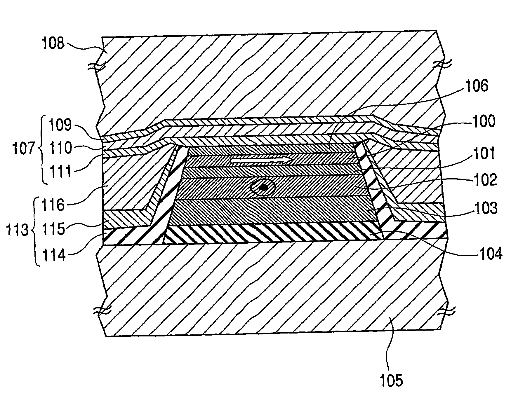
[0068]FIG. 8 illustrates a spin valve of a sensor for reading a magnetic medium according to an exemplary, non-limiting embodiment of the present invention. A spacer 101 is positioned between a free layer 100 and a pinned layer 102. As discussed above with respect to the related art, an external field is applied to the free layer 100 from a recording medium, such that the free layer magnetization direction can be changed. The pinned layer 102 has a fixed magnetization direction.

[0069]The pinned layer 102 can...


PUM

PropertyMeasurementUnit
diameteraaaaaaaaaa
thicknessaaaaaaaaaa
thicknessaaaaaaaaaa

Abstract

A magnetoresistive read head includes a spin valve having a multi-layer in-stack bias and side shields to substantially reduce the undesired flux from adjacent bits and tracks, as well as from the transverse field of the recording medium itself. At least one free layer is spaced apart from at least one pinned layer by a spacer. Above the free layer, a capping layer is provided, followed by the in-stack bias, which includes a non-magnetic conductive layer, a ferromagnetic layer having a magnetization fixed by an anti-ferromagnetic layer, and a stabilizing ferromagnetic layer. Additionally, a multilayered side shield is provided, including a thin insulator, a soft buffer layer and a soft side shield layer. As a result, the free layer is shielded from the undesired flux, and recording media having substantially smaller track size and bit size.

Description

TECHNICAL FIELD[0001]The present invention relates to the field of a read element of a magnetoresistive (MR) head, and a method of manufacture therefor. More specifically, the present invention relates to a spin valve of an MR read element having a side shield that provides bias stabilization.BACKGROUND ART[0002]In the related art magnetic recording technology such as hard disk drives, a head is equipped with a reader and a writer. The reader and writer have separate functions and operate independently of one another, with no interaction therebetween.[0003]FIGS. 1 (a) and (b) illustrate related art magnetic recording schemes. In FIG. 1(a), a recording medium 1 having a plurality of bits 3 and a track width 5 has a magnetization parallel to the plane of the recording media. As a result, a magnetic flux is generated at the boundaries between the bits 3. This is also commonly referred to as “longitudinal magnetic recording media” (LMR).[0004]Information is written to the recording medi...

Claims


Application Information

Patent Timeline
Patent Type & Authority Patents(United States)
IPC IPC(8): G11B5/33A61K6/083A61K6/896G11B5/127G11B5/39
CPCG11B5/39G11B5/1278
Inventor SBIAA, RACHIDSATO, ISAMU
Owner TDK CORPARATION
Why Eureka
Try Eureka