
Plastic chassis and plasma display device including the same

a display device and plastic chassis technology, applied in the field of plastic chassis and plasma display devices, can solve the problems of increasing the manufacturing cost of metal chassis, the difficulty of directly the difficulty of mounting circuit elements on the rear surface of a pdp, so as to reduce the manufacturing cost of the display device

Inactive Publication Date: 2009-10-06
SAMSUNG SDI CO LTD
View PDF4 Cites 13 Cited by
  • Summary
  • Abstract
  • Description
  • Claims
  • Application Information

AI Technical Summary

Benefits of technology

The patent text describes a plastic chassis for a display device that can help reduce manufacturing costs. The chassis is made of a single piece of plastic that includes a base and a support frame. The support frame is integrally formed with the base and is spaced from it. This design helps to save money and make the manufacturing process more efficient. The chassis can be made using injection molding. Overall, this invention provides a cost-effective solution for creating plastic display devices.

Problems solved by technology

Accordingly, it is difficult to directly mount a circuit element on the rear surface of a PDP.
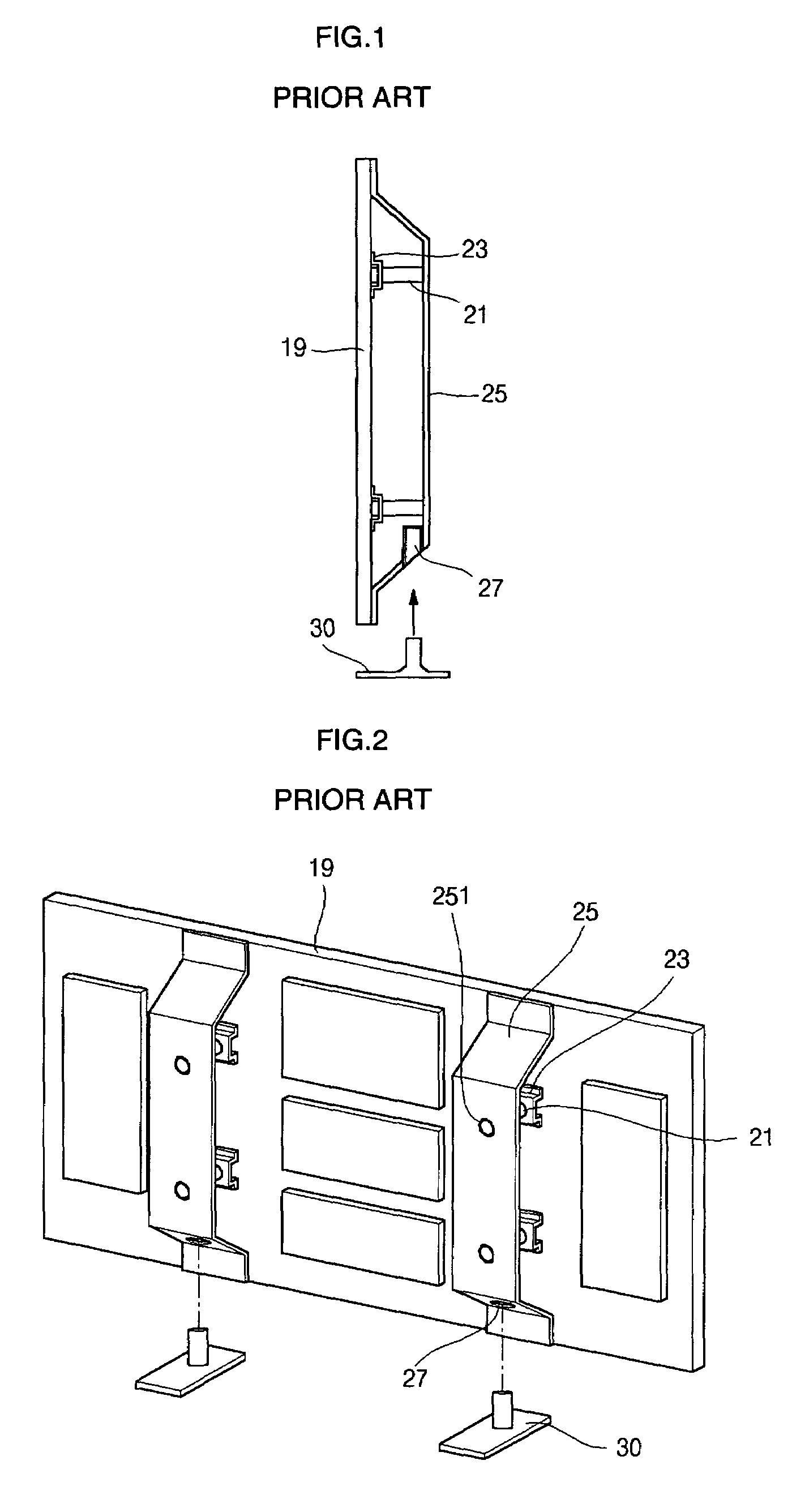
In accordance with a recent increase in sizes of plasma display devices, the weight of a metal chassis base used in the chassis has increased, increasing the manufacturing cost of the metal chassis.
However, there is a limit to thickness reduction of the metal chassis base which functions as the frame for mounting the panel and a protective circuit board.
In this structure, since the components are separately formed and then coupled with one another, the cost required for assembling the components in this manner is increased.

Method used


Image

  • Plastic chassis and plasma display device including the same
  • Plastic chassis and plasma display device including the same
  • Plastic chassis and plasma display device including the same

Examples


Embodiment Construction

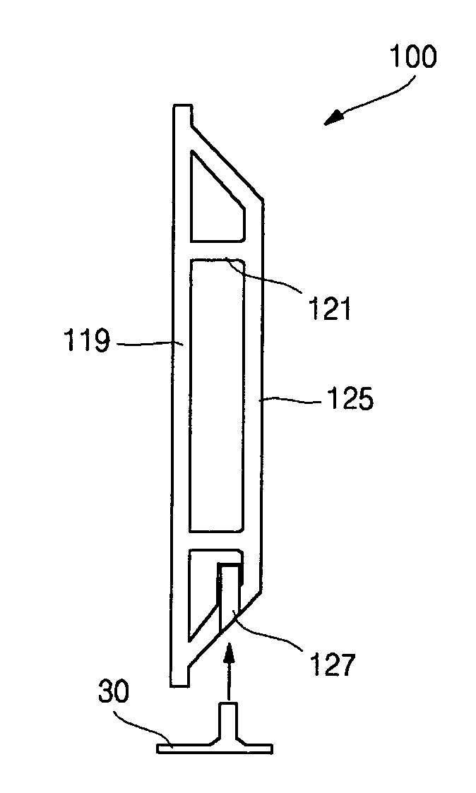
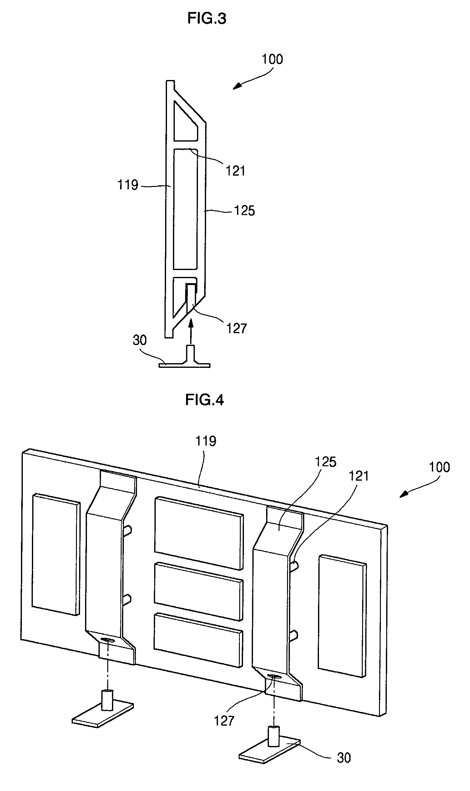
[0023]Referring to FIGS. 3 and 4, a support frame 125 and the chassis base 119 are integrally formed without using a separate coupling means. The support frame 125 has a wide band shape and is fixed at upper and lower sides of the chassis base 119 at either end of the support frame. Accordingly, a boss or a screw for coupling the elements is not necessary. In addition, as a support body, a plastic reinforcement pillar 121 is integrally formed between the chassis base 119 and the support frame 125 and functions as a boss.

[0024]A guide stand hole 127 is formed in a lower portion of the support frame 125 where the plasma display device is normally mounted on a guide stand 30.

[0025]The chassis 100 having the integrally formed chassis base 119 and support frame 125, has a structure such that casting mold for forming the plastic chassis by a pouring or molding method may be divided into at least two portions in accordance with the shape of the chassis to be formed, as would by typically u...


PUM


Abstract

A plastic chassis for a display device, the plastic chassis having an integrally formed chassis base and support frame. A support body joins the chassis base and the support frame.

Description

BACKGROUND OF THE INVENTION[0001]This application claims priority to and the benefit of Korean Patent Application No. 10-2005-0046850, filed on Jun. 1, 2005, in the Korean Intellectual Property Office, the entire content of which is incorporated herein by reference.[0002]1. Field of the Invention[0003]The present invention relates to a plasma display device, and more particularly, to a plasma display device including a plastic chassis.[0004]2. Description of Related Art[0005]Recently, improvements for flat panel display devices have been actively researched. An example of such a flat panel display device is a plasma display device which uses a plasma display panel (PDP). A conventional PDP includes electrodes on two facing substrates, wherein the two substrates overlap at a predetermined interval. A discharge gas is injected between the two substrates, and the two substrates are sealed.[0006]Since a plasma display device can be manufactured to be thinner than a cathode ray tube (CRT...

Claims


Application Information

Patent Timeline
Patent Type & Authority Patents(United States)
IPC IPC(8): H01J17/49G09F9/00H04N5/655
CPCH05K5/02H01J11/20
Inventor JEONG, KWANG JIN
Owner SAMSUNG SDI CO LTD
Learn More