Membrane coupling in a compact design

a technology of membrane coupling and compact design, applied in the direction of yielding coupling, friction clutch, clutch, etc., can solve the problem of relatively large construction space and achieve the effect of compact construction space and weight reduction

Active Publication Date: 2009-10-06
HACKFORTH GMBH
View PDF22 Cites 0 Cited by
  • Summary
  • Abstract
  • Description
  • Claims
  • Application Information

AI Technical Summary

Benefits of technology

[0008]It is the task of the present innovation to reconfigure a membrane coupling of the type stated initially, in such a manner that it takes up a more compact construction space and, at the same time, its weight is reduced.
[0011]Furthermore, a constellation of the components that is symmetrical to a high degree is achieved by means of the arrangement of the membrane packs according to the innovation. This constellation contributes to increasing the quiet running of the coupling, and to balancing out great offset between the coupling halves.
[0013]It is practical if the break-throughs in the membrane packs are configured as bores whose diameters are greater than the diameters of the pin / sleeve arrangements. The tensions in the region of the break-throughs are reduced by means of these measures, and the durability of the coupling is thereby increased.

Problems solved by technology

A disadvantage of the previously known membrane coupling is its relatively large construction space.

Method used


Image

  • Membrane coupling in a compact design
  • Membrane coupling in a compact design
  • Membrane coupling in a compact design

Examples


Embodiment Construction

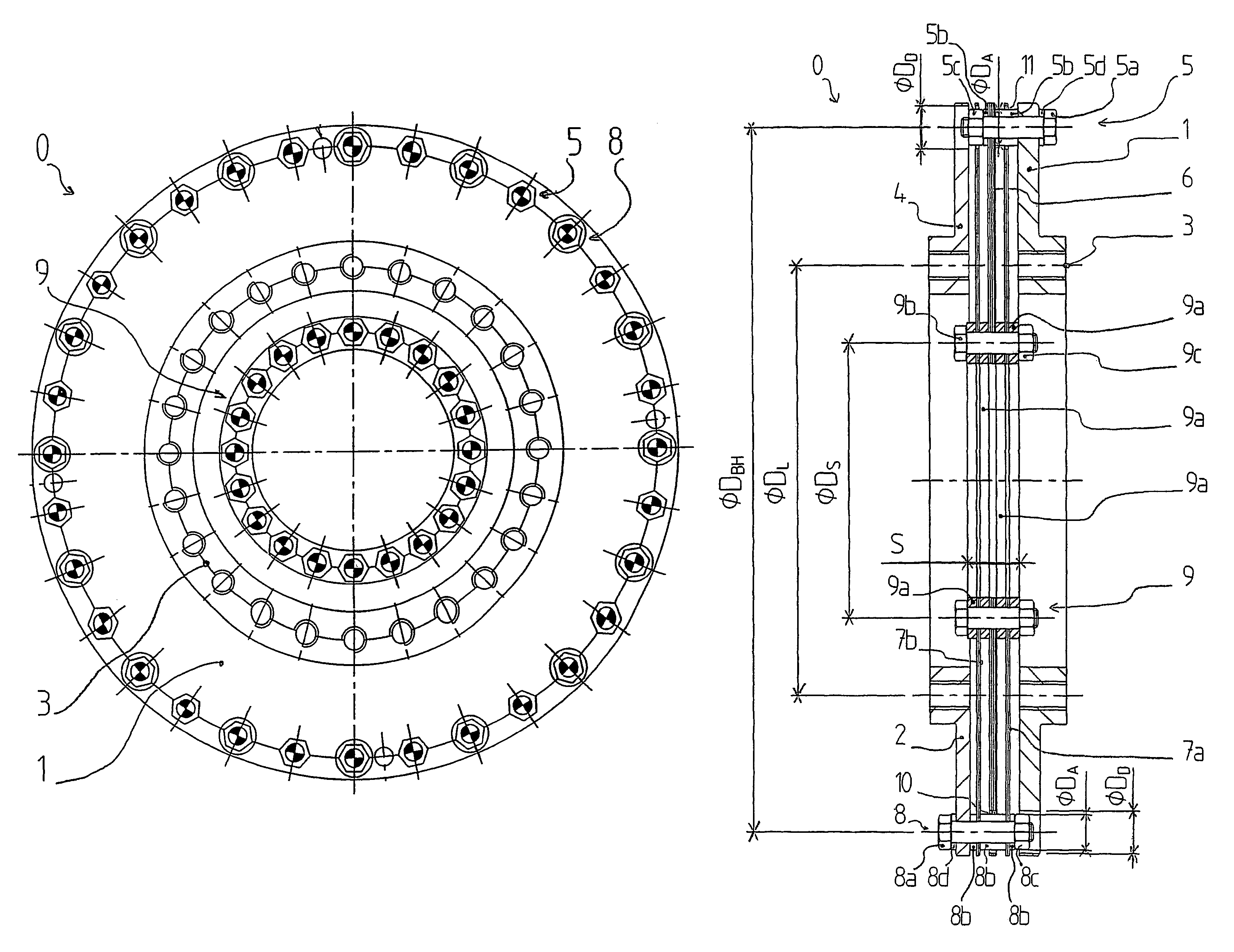
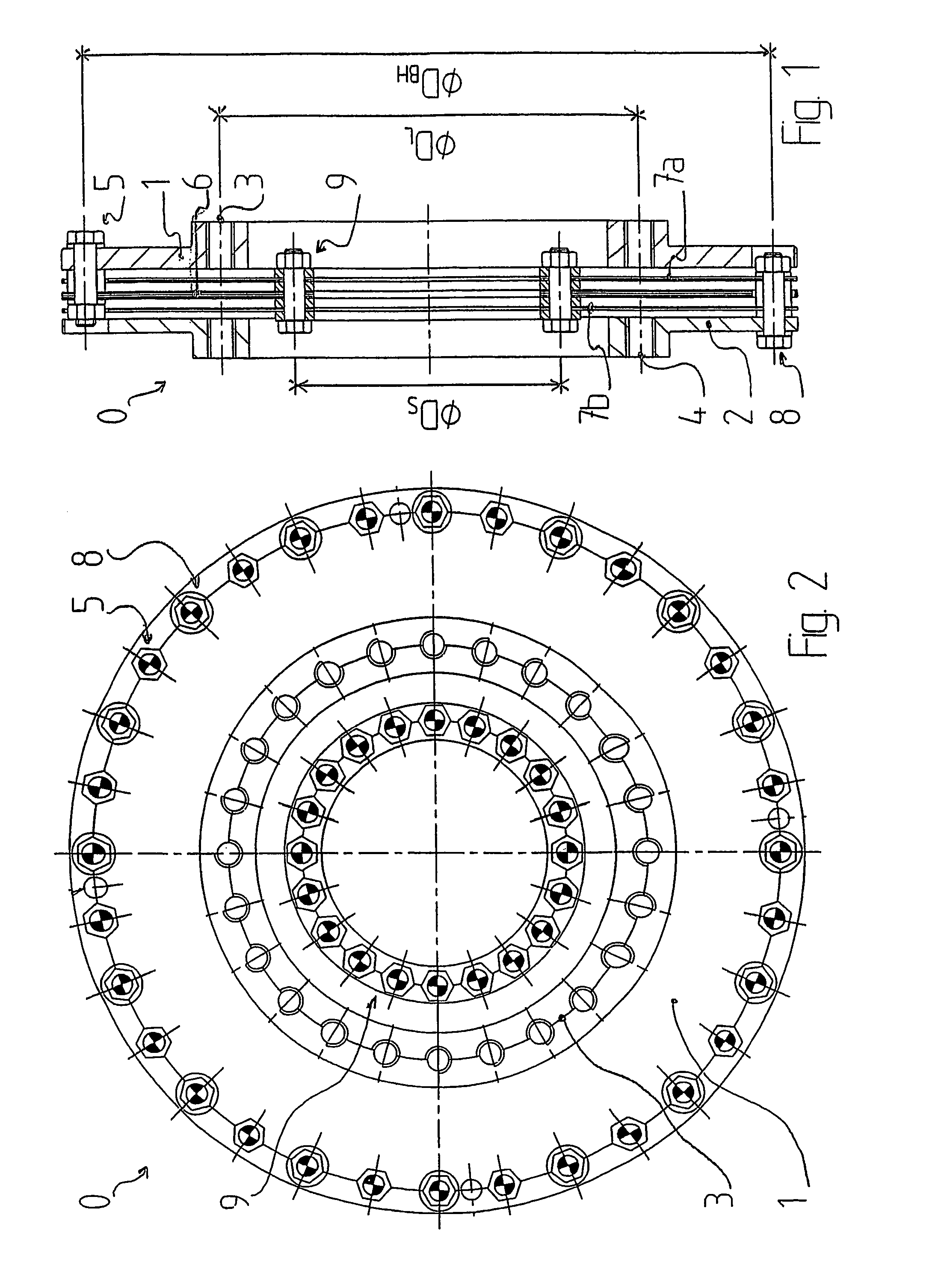
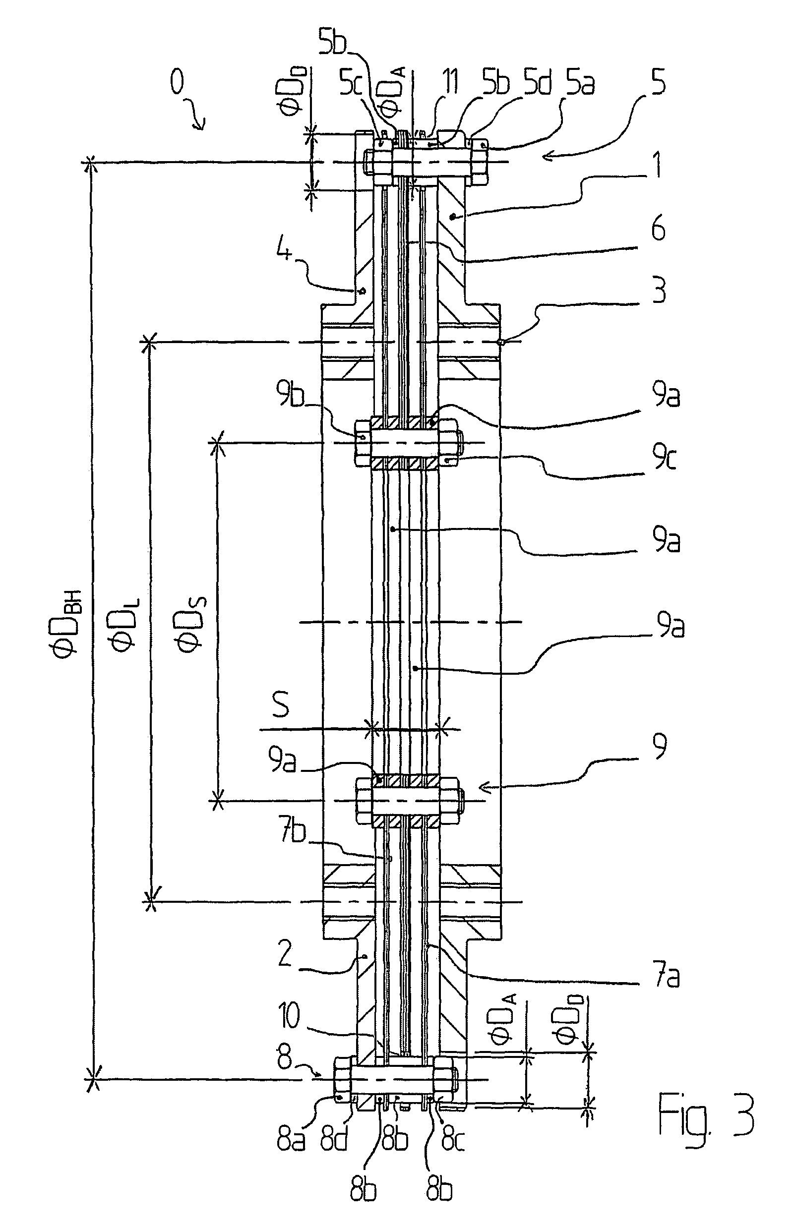
[0020]The membrane coupling, as a whole, is designated with the reference symbol 0. It comprises an input flange 1 and an output flange 2. The flanges 1, 2 are provided with an input perforated circle 3 and an output perforated circle 4, respectively, by way of which the membrane coupling 0 can be coupled to machine elements of a drive train that are disposed ahead of or following it. The two perforated circles 3, 4 are concentric when the flanges are aligned. In the exemplary embodiment, the two perforated circles 3, 4 have the same diameter DL. For certain purposes of use, it is also possible to provide perforated circles 3, 4 with different diameters DL. Pin / sleeve arrangements of a first type 5 are disposed on a greater diameter DBH.

[0021]A pin / sleeve arrangement of a first type 5 comprises a screw 5a, two sleeves 5b, a nut 5c, and a washer 5d. An input membrane pack 6 is braced relative to the input flange 1 by means of the pin / sleeve arrangement of a first type 5. The input me...


PUM


Abstract

A membrane-type coupling includes an input flange and an output flange which are interconnected via membrane packs in order to transmit torque in such a way that an input membrane pack is braced to the input flange, two output membrane packs that are connected in parallel are braced to the output flange, and the membrane packs are braced to one another with the aid of a clamping set composed of clamping rings. In order to reduce the volume and weight of such a membrane-type coupling, the input membrane pack is disposed between the two output membrane packs.

Description

CROSS REFERENCE TO RELATED APPLICATIONS[0001]Applicant claims priority under 35 U.S.C. §119 of German Application No. 20 2004 006 442.1 filed Apr. 23, 2004. Applicant also claims priority under 35 U.S.C. §365 of PCT / EP2005 / 003479 filed Apr. 2, 2005. The international application under PCT article 21(2) was not published in English.BACKGROUND OF THE TNVENTION[0002]1. Field of the Invention[0003]The present innovation relates to a membrane coupling having an input flange and having an output flange, which are connected with one another for the purpose of transferring torque, by way of membrane packs, in such a manner that an input membrane pack is braced relative to the input flange, that two output membrane packs that are switched in parallel are braced relative to the output flange, and that the membrane packs are braced relative to one another by means of a bracing set composed of clamping rings.[0004]2. Description of the Related Art[0005]U.S. Pat. No. 4,492,583 A discloses a coup...

Claims


Application Information

Patent Timeline
IPC IPC(8): F16D3/00F16D3/79
CPCF16D3/79F16D3/72F16D3/50F16D13/64
Inventor UCKERT, HEINRICH
Owner HACKFORTH GMBH
Why Eureka
Try Eureka