
Cable management system for a movable display device

a management system and display device technology, applied in the direction of curtain suspension devices, electric apparatus casings/cabinets/drawers, instruments, etc., can solve the problems of inability to offer a robust management system for managing the electrical cabling of movable display devices, affecting the efficiency of display devices, and affecting the use of limited areas

Inactive Publication Date: 2009-09-22
SHAHROKHI FARSHAD
View PDF13 Cites 11 Cited by
  • Summary
  • Abstract
  • Description
  • Claims
  • Application Information

AI Technical Summary

Benefits of technology

"The present invention is a display support system that allows for the movement and flexibility of a display device. The system includes a track system, a support member, and a cable management system. The support member is able to rotate around an axis perpendicular to the display movement path and has a stop to prevent excessive rotation. The track system includes at least one rail and at least one wheel for moving the display along the path. The system also includes one or more lights along the track system. The technical effects of this invention include improved mobility, functionality, and aesthetics for display devices."

Problems solved by technology

In today's world where space has become a commodity, efficient use of limited areas for display devices remains a challenge for both economic and practical reasons.
However, currently available moveable display systems, such as the one disclosed in U.S. Pat. No. 6,739,096, do not offer a robust system for managing the electrical cabling of movable display devices.
Otherwise, electrical cables may become tangled through repeated movement.
Tangled wires can interfere with the movement of the display device, impede signal transmission, or lead to the disconnection of an electrical signal.
Exposed wires suffer from increased wear-and-tear and can also be a safety hazard.

Method used


Image

  • Cable management system for a movable display device
  • Cable management system for a movable display device
  • Cable management system for a movable display device

Examples


Embodiment Construction

[0014]Embodiments of the invention are discussed in detail below. In describing embodiments, specific terminology is employed for the sake of clarity. However, the invention is not intended to be limited to the specific terminology so selected. While specific exemplary embodiments are discussed, it should be understood that this is done for illustration purposes only. A person skilled in the relevant art will recognize that other components and configurations can be used without parting from the spirit and scope of the invention.

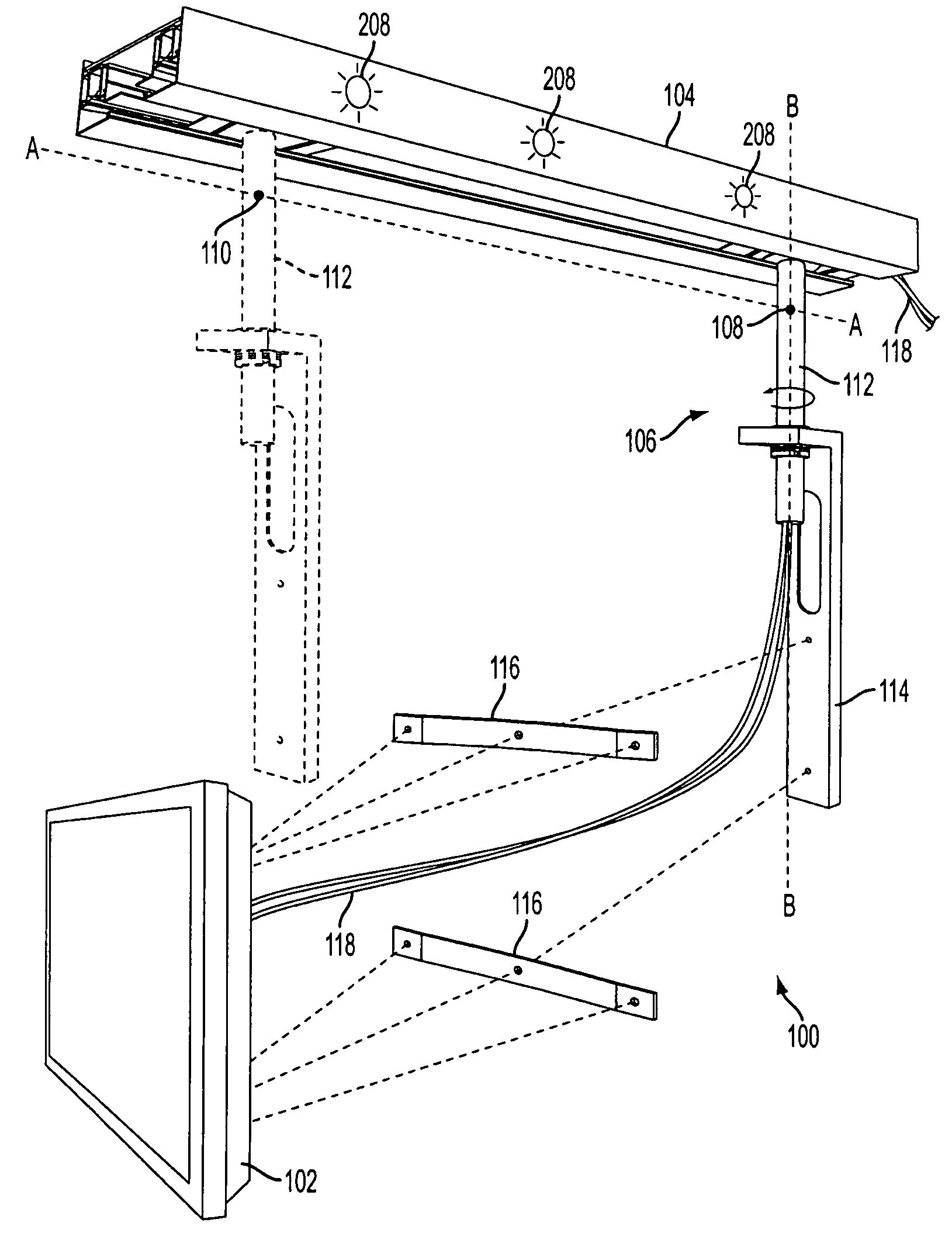
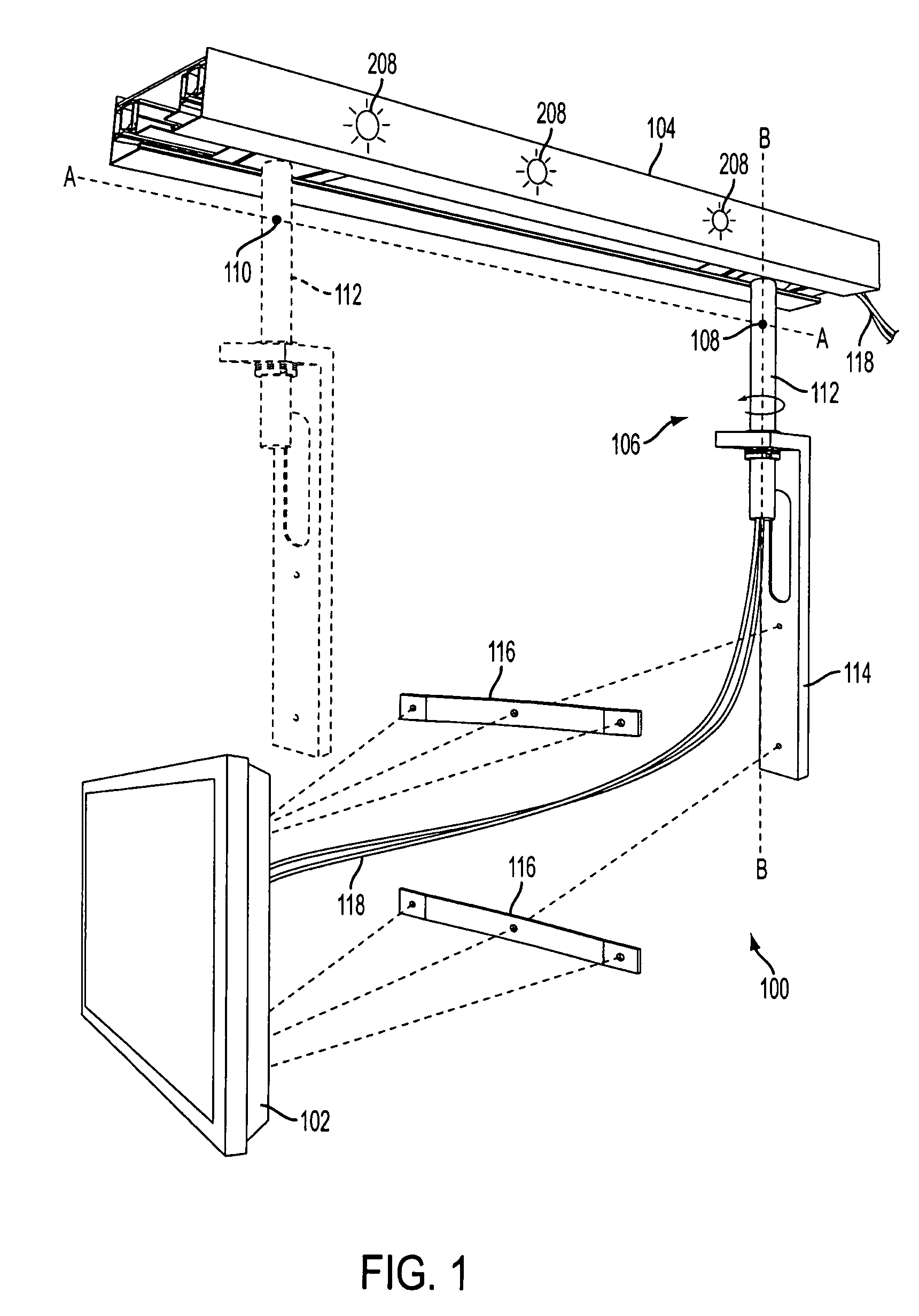
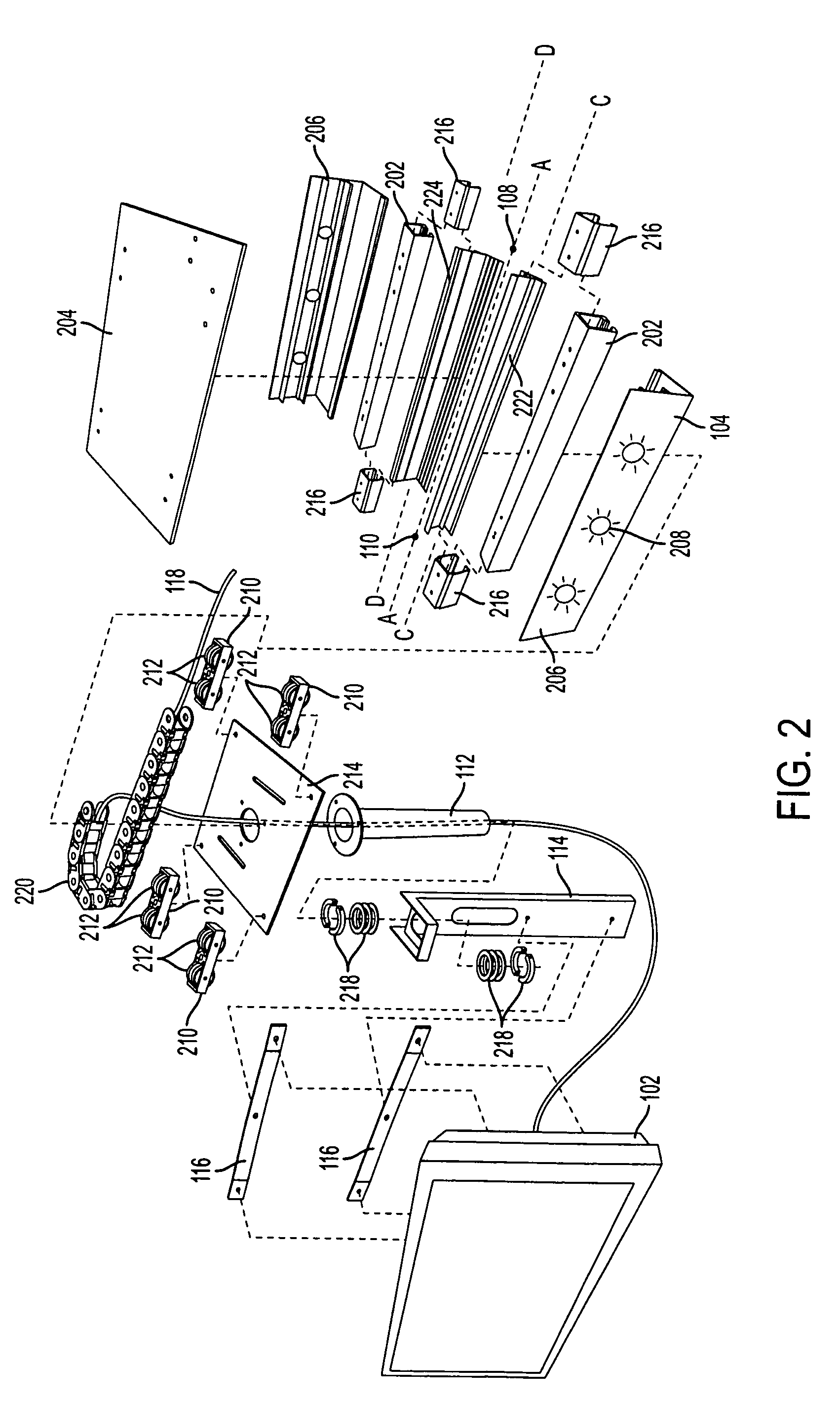
[0015]FIG. 1 shows a perspective view of a display support system 100 for a movable display device 102 according to an exemplary embodiment of the present invention. The display support system 100 includes a track system 104, a cable management system disposed in the track system (shown in FIGS. 2, 4A and 4B), and a support member 106, which is moveably engaged with the track system 104 for supporting the movement of the display device 102 along a display mo...


PUM


Abstract

A support system for a display device comprise a track system that defines a display movement path for movement of the display device. A support member that is movably engaged with the track supports the movement of the display device along the movement path. A cable management system has a cable of predetermined length that electrically connects to the display device and a flexible cable carrier disposed in the track system carries the cable. The flexible cable carrier has a fixed end along a first cable movement path and a moving end along a second cable movement path that is distinct from the first cable movement path.

Description

BACKGROUND OF THE INVENTION[0001]Advances in technology have created an increasing need for presenting useful data and content via display devices used in computers and televisions as well as medical or monitoring units. Moreover, convergence of data and content is leading the way for more versatile display devices where for example, computer information and high definition content can be viewed on a single display device. The most important object of the living room has undergone a substantial transformation in the last few decades. The flattening of the TV screen and the possibility to integrate it with the computer has started to shape the way in which most spaces are organized.[0002]Space considerations has always been paramount in the design and use of display devices. In today's world where space has become a commodity, efficient use of limited areas for display devices remains a challenge for both economic and practical reasons. For example, for a city apartment-dweller, it i...

Claims


Application Information

Patent Timeline
Patent Type & Authority Patents(United States)
IPC IPC(8): H05K5/00A47B81/00A47B97/00A47H1/10H05K7/00B66B9/00E04H6/06G09F7/18
CPCF16G13/16F16M11/04F16M11/041F16M11/08F16M11/2092H02G11/006F16M11/425F16M13/02H02G3/0475H02G11/003F16M11/42F16M2200/065Y10S248/917
Inventor SHAHROKHI, FARSHAD
Owner SHAHROKHI FARSHAD
Learn More