
Endoscope system with insertion direction changing guides

a technology of insertion direction and guide, which is applied in the field of endoscope systems, can solve the problems of difficult adroit placement of the insertion unit into the target region, and achieve the effect of improving the accuracy of insertion

Inactive Publication Date: 2009-09-22
OLYMPUS CORP
View PDF22 Cites 32 Cited by
  • Summary
  • Abstract
  • Description
  • Claims
  • Application Information

AI Technical Summary

Benefits of technology

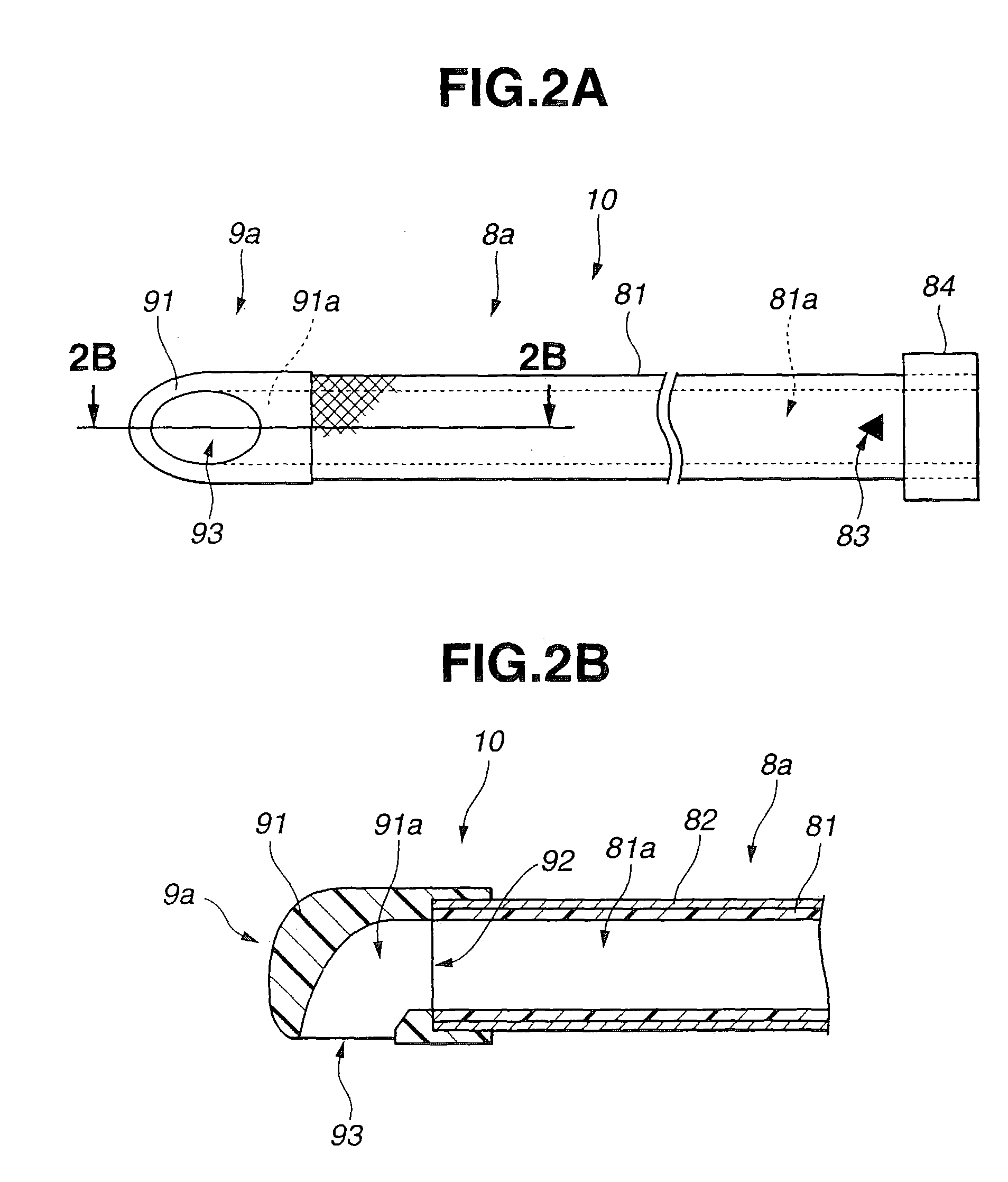
[0009]An endoscope system includes an endoscope and an insertion unit guide member. The endoscope includes an elongated insertion unit that has a bending section formed adjacently to a distal section thereof. The insertion unit guide member comprises a plurality of tubular members that is placed in a pipe. Each of the tubular members includes a guide channel having a predetermined diameter that permits related tubular member or the insertion unit to smoothly pass through the guide channel. The plurality of tubular members exhibits predetermined degrees of flexibility and has predetermined lengths. At least one tubular member has a distal cover member that serves as a direction changing means for changing the advancing direction in which the insertion unit advances through the guide channel.

Problems solved by technology

This makes it hard to adroitly insert the insertion unit into the target region.

Method used


Image

  • Endoscope system with insertion direction changing guides
  • Endoscope system with insertion direction changing guides
  • Endoscope system with insertion direction changing guides

Examples


first embodiment

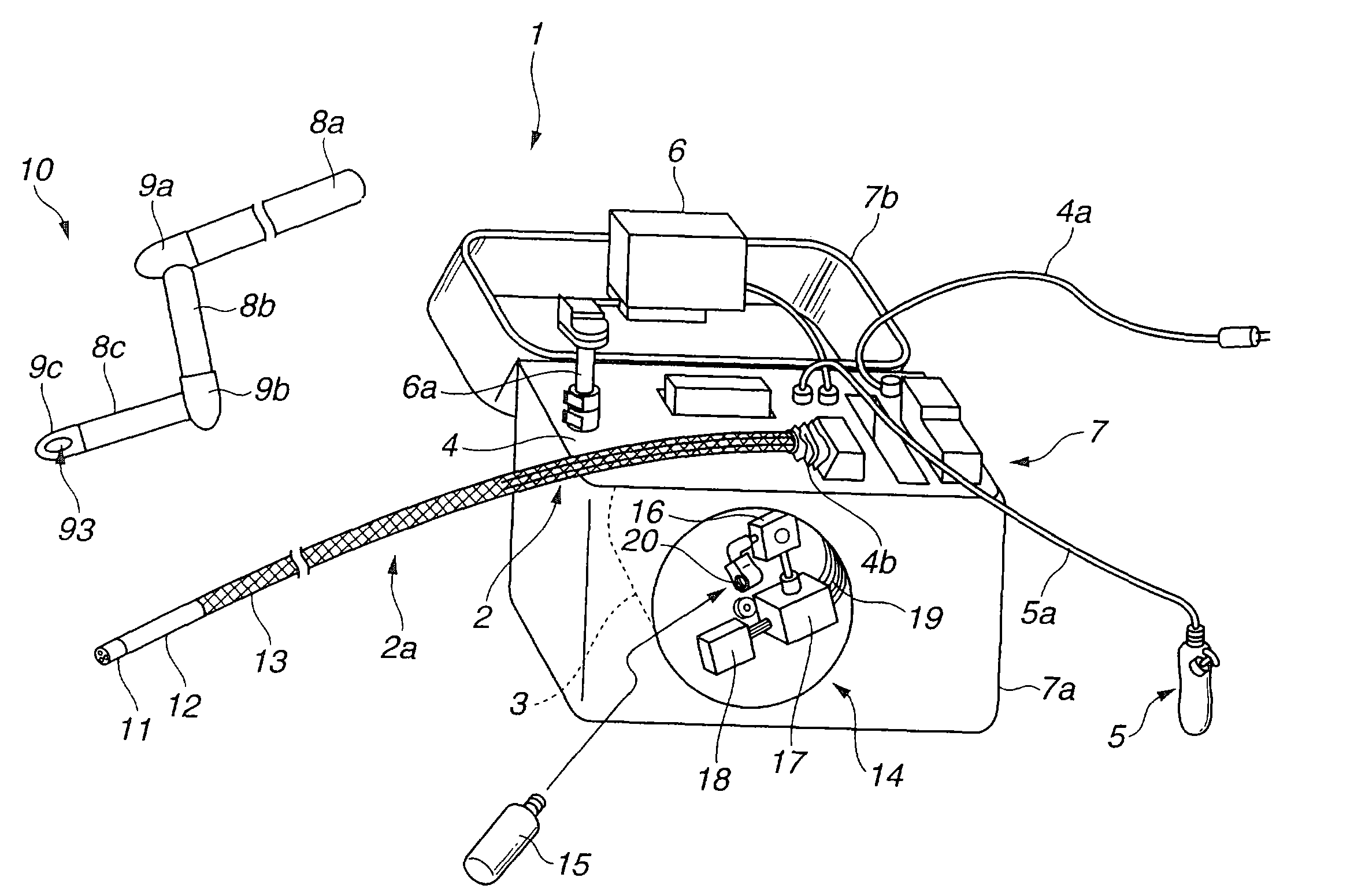
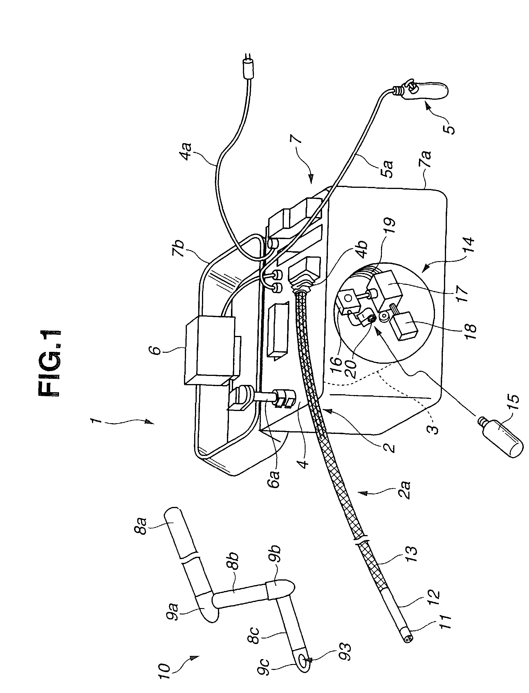
[0053]As shown in FIG. 1, an endoscope system 1 in accordance with the present embodiment comprises an endoscope 2 for, for example, industrial use, a drum 3, a front panel 4, a remote controller 5, a monitor 6, a container case 7, and an insertion unit guide member 10.

[0054]The endoscope 2 includes an elongated insertion unit 2a that has flexibility. The drum 3 has a periphery 3a about which the insertion unit 2a is wound. The drum 3 is held in a frame serving as a support, which is not shown, so that it can be freely rotated.

[0055]The front panel 4 is placed on the top of the frame. An AC cable 4a over which main power can be supplied, various switches, connectors, and an air supply / exhaust duct are exposed on the front panel 4.

[0056]The remote controller 5 has operation switches including a joystick 5a that is used to direct angling, and is connected to the front panel 4 over a cable 5a so that it can be disconnected freely. The monitor 6 is supported by a stretchable / contractile...

second embodiment

[0100]As shown in FIG. 10, an endoscope system 101 in accordance with the present embodiment comprises an endoscope 102, a drum 103, a frame 104, and a remote controller 105. Reference numeral 106 denotes a controller. The endoscope 102 has an elongated insertion unit 102a. The insertion unit 102a is wound about the internal surface of the drum 103. The frame 104 is a support that holds the drum 103 so that the drum 103 can rotate freely. The remote controller 105 has operation switches including a joystick 105a that is used to direct the endoscope 102 to angle the insertion unit.

[0101]The endoscope system 101 includes a monitor 110 on which an endoscopic image picked up by the endoscope 102 is displayed, an AC adapter 111 serving as a power supply, and a personal computer (112 in FIG. 15 to be described later). The personal computer 112 is connected to the endoscope system via a PC connector that is not shown, and used to modify control data or the like to be transmitted to a valve...


PUM


Abstract

An endoscope system includes an endoscope and an insertion unit guide member. The endoscope has an elongated insertion unit whose bending section adjoins a distal section thereof. The insertion unit guide member comprises a plurality of tubular members to be placed in a pipe. Each of the tubular members has a guide channel having a predetermined diameter that permits other tubular member or the insertion unit to smoothly pass through the guide channel. The plurality of tubular members has predetermined degrees of flexibility and predetermined lengths. At least one of the tubular members has a member that changes the advancing direction in which the insertion unit is advanced through the guide channel.

Description

[0001]This application claims the benefit of Japanese Application Nos. 2002-205824 filed on Jul. 15, 2002 and 2002-212853 filed on Jul. 22, 2002, the contents of which are incorporated by reference.BACKGROUND OF THE INVENTION[0002]1. Field of the Invention[0003]The present invention relates to an endoscope system including an endoscope that has an elongated insertion unit.[0004]2. Description of the Related Art[0005]In general, endoscopes adaptable to industrial use or medical use have an elongated insertion unit that is inserted into a lumen. The insertion unit of this type of endoscope has a bending section formed adjacently to a distal section thereof. By bending the bending section, the endoscope can be angled in any observational direction.[0006]For example, there is the work of inserting the elongated insertion unit of an endoscope for industrial use into the deep end of a tortuous pipe that has a plurality of elbows. During the work, the insertion unit is passed the elbows by...

Claims


Application Information

Patent Timeline
IPC IPC(8): A61B1/00A61B1/04G02B23/24
CPCG02B23/2476
Inventor HIRATA, YASUO
Owner OLYMPUS CORP
Learn More