
Low profile clamp for embroidery machine

a technology of embroidery machine and clamping mechanism, which is applied in the field of embroidery machines, can solve the problems of large and bulky clamping mechanism, persistent problem, and substantial damage to embroidery machines, and achieve the effect of simplifying the clamping mechanism

Active Publication Date: 2009-09-08
VILTRAKIS VYTENIS J +1
View PDF6 Cites 9 Cited by
  • Summary
  • Abstract
  • Description
  • Claims
  • Application Information

AI Technical Summary

Benefits of technology

[0005]It is another object of at least one embodiment of the present invention to provide a clamping system that will not damage the embroidery machine if the clamp is moved along a path traversing the space between the presser feet and needles, and the throat plate of an embroidery machine.
[0006]Another object of at least one embodiment is to provide an improved clamping mechanism for an embroidery machine that applies a clamping force between clamping windows with a simplified clamping mechanism.
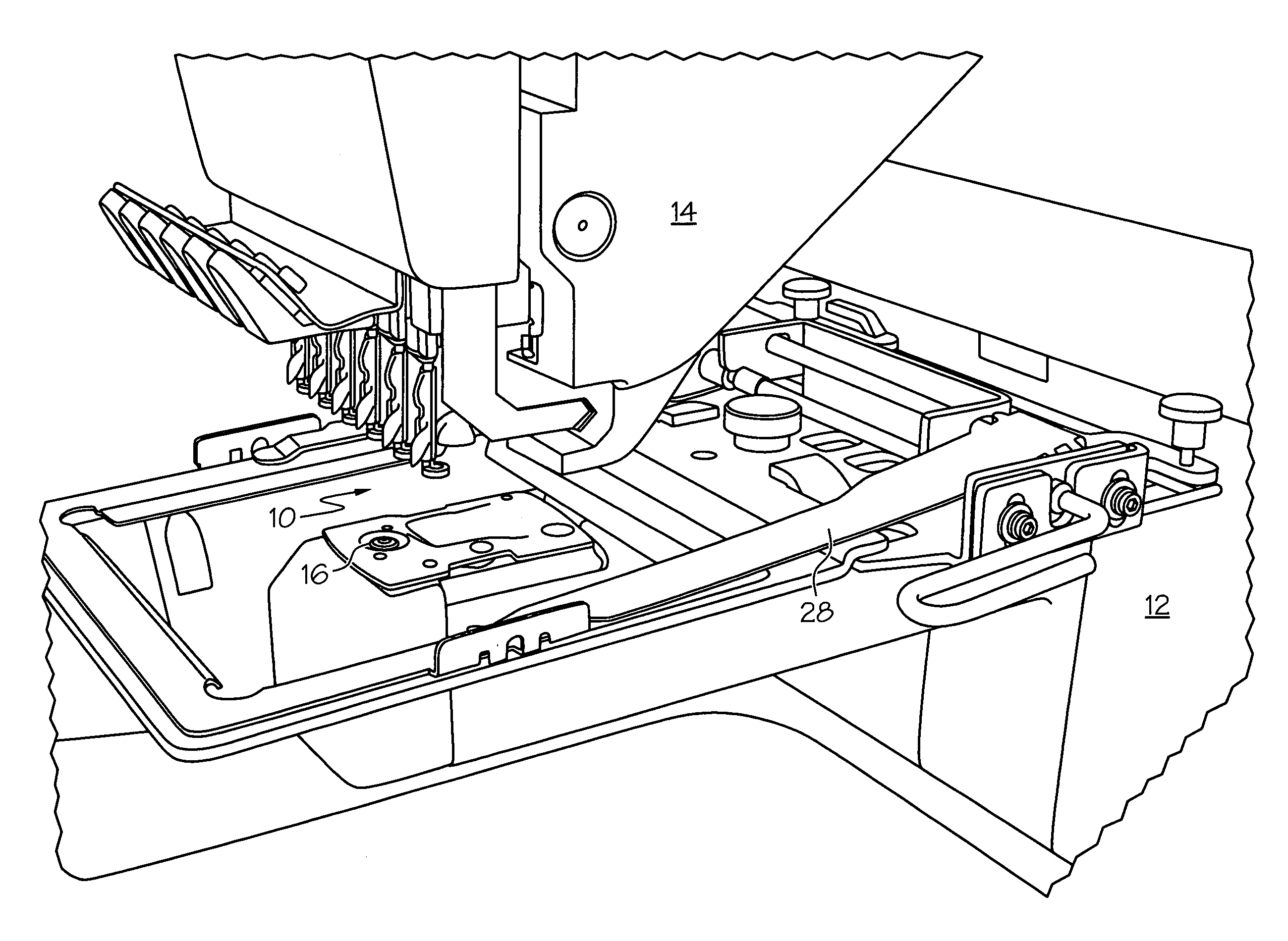
[0008]To achieve one or more of these objects, one embodiment of the present invention includes an embroidery machine with a base, a throat plate, a head extending outwardly from the base, and a plurality of presser feet extending from the head toward the throat plate. Each of the presser feet are movable relative to the head toward and away from the throat plate and are associated with a needle adapted to pass through an article to be embroidered. Each of the presser feet also are movable between a retracted position in which the presser feet are spaced by a predetermined space from the throat plate and an extended position in which the presser feet are adapted to engage an article to be embroidered. The article to be embroidered is positioned in a sewing location between the presser feet and the throat plate while the needles pass through the article to be embroidered. A first clamping window is provided with a first embroidery opening. A a second clamping window with a second embroidery opening is also provided with the first and second clamping windows being movable between first relative positions in which the second clamping window is spaced from the first clamping window and second relative positions in which the first and second openings are aligned with each other. The first and second clamping windows are cooperatively operative to clamp an article to be embroidered in the sewing location between the presser feet and the throat plate when the clamping windows are in their second relative positions. A clamp is provided for effectuating relative movement between the first and second clamping windows and applying a compressive force between the first and second windows when the clamping windows are in their second relative positions. When in these second positions, the clamping windows securing an article to be embroidered therebetween. The clamp is secured to the panagraph. The panagraph is operative to effectuate two dimensional movement to the clamp and to move an article secured between the clamping windows relative to the needles in two-directional movement perpendicular to the predetermined space between the presser feet and the throat plate. The clamp is dimensioned and configured to pass through the predetermined space between the presser feet and the throat plate so as to prevent damage if the panagraph positions the clamp in the space between the plates and the throat plate.
[0020]In another embodiment, the clamp is d dimensioned and configured to pass through a space between presser feet and a throat plate on an embroidery machine so as to prevent damage to the embroidery machine if the clamp is positioned between the presser feet and the throat plate of an embroidery machine.

Problems solved by technology

While such holding clamps are been used for many years, one problem has persisted.
Since it is necessary for a holding clamp to apply a compressive force to hold a article being embroidered between a pair of clamping windows, mechanism used to apply the clamping force have relatively large and bulky.
This profile thickness of the prior art holding clamps has lead to considerable problems, including substantial damage to embroidery machines.
This is particularly problematic during initialization of the panagraph controls, as the panagraph my move the clamp throughout the panagraph's entire X-Y movement Unfortunately, this space generally is less than the profile of the clamp, and the thick profile portion of the fabric clamp may be moved into the presser feet and needles, both of which are relatively fragile.
As a consequence of this movement, substantial machine damage results, necessitating expensive repairs and downtime.

Method used


Image

  • Low profile clamp for embroidery machine
  • Low profile clamp for embroidery machine
  • Low profile clamp for embroidery machine

Examples


Embodiment Construction

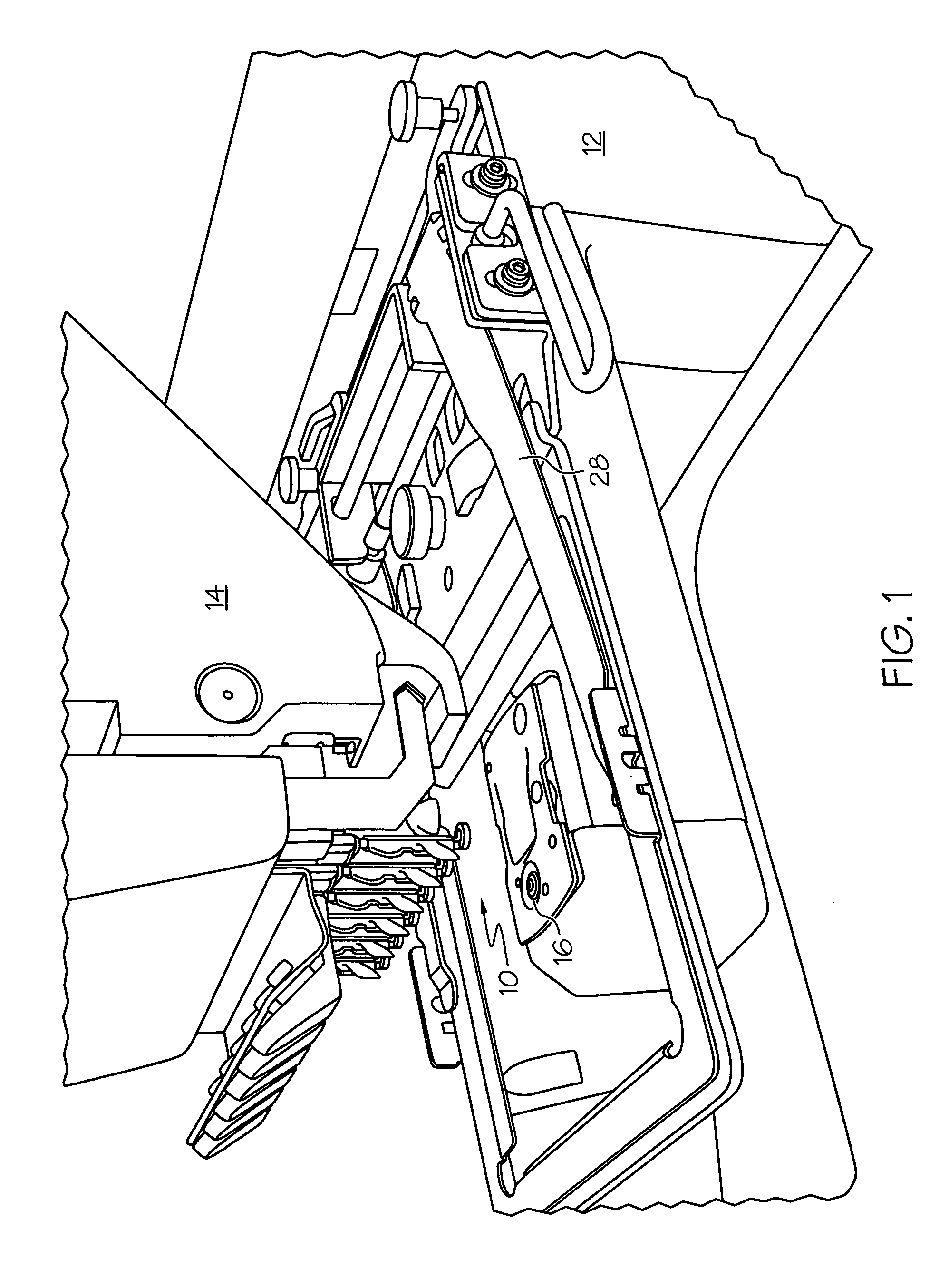
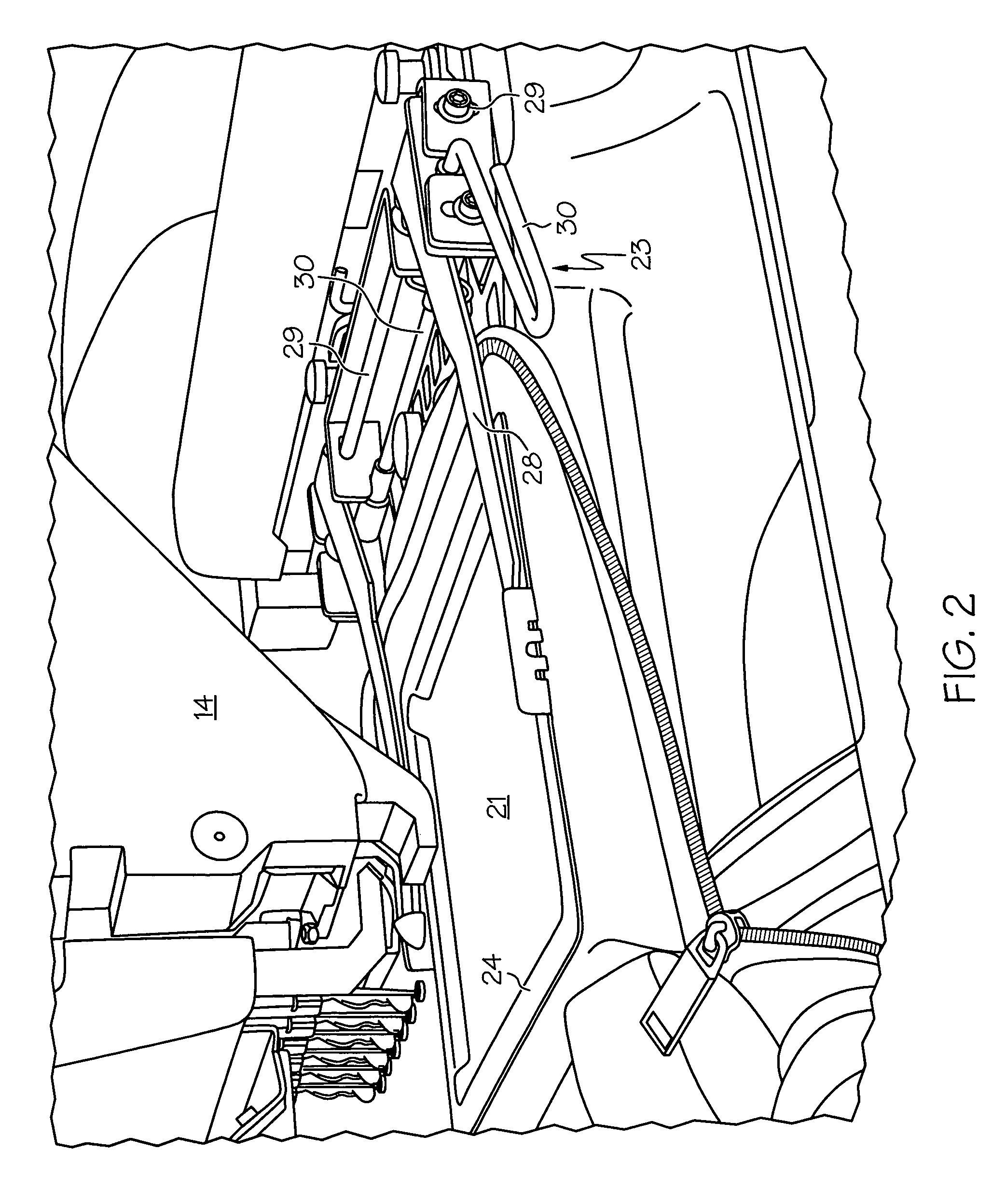
[0036]Referring now to the drawings, FIG. 1 shows one form of an embroidery machine 10 constructed in accordance with the principles of the present invention. The machine, which is conventional except for the low profile clamp, which is described in detail below, includes a base 12, which supports a head 14 extending outwardly therefrom. A plurality of presser feet, collectively referenced by the numeral 16, extend downwardly from the head 14. As those skilled in the art will readily appreciate, the presser feet are movable from a first retracted position (shown in FIG. 1) to an extended position where they engage an article to be embroidered. Each of the presser feet 16 is associated with a needle 18. The outer end of each of the needles 18 pass though a fabric or other article (not shown in FIG. 1, see FIG. 2) interposed between the presser foot 16 and a throat plate 20. As will be apparent to those skilled in the art, the lower (in the illustrated orientation) end of the needles ...


PUM


Abstract

A low profile clamp for an embroidery machine uses resilient arms that function as a leaf spring to transmit compressive closing forces to secure articles to be embroidered between clamping windows. A roller is moved in an arcuate path to apply bending stresses to clamp arms. The low profile of the clamp allows it to pass between the presser feet and throat plate protecting the presser feet and needles from serious damage if the panagraph moves the body of the clamp in the space between presser feet and throat plate during machine initialization or at any other time.

Description

RELATED APPLICATIONS[0001]This application claims the benefit of U.S. Provisional Patent Application Ser. No. 60 / 608,578, filed Sep. 10, 2004, the disclosures of which is incorporated herein by reference.TECHNICAL FIELD[0002]The present invention relates generally to embroidery machines and more specifically to a clamp for securing articles as they are being embroidered. The invention will be disclosed in connection with a low profile clamp that prevents damage to the embroidery machine if the panagraph moves the clamp into the space between the presser feet and the throat plate.BACKGROUND OF THE INVENTION[0003]In the sewing and embroidery industry, fabric holding clamps are widely used for holding individual work pieces during the embroidery process. While such holding clamps are been used for many years, one problem has persisted. Since it is necessary for a holding clamp to apply a compressive force to hold a article being embroidered between a pair of clamping windows, mechanism...

Claims


Application Information

Patent Timeline
Patent Type & Authority Patents(United States)
IPC IPC(8): D05C9/04D05B39/00
CPCD05C9/04D05B39/00
Inventor VILTRAKIS, VYTENIS JMASON, MARK
Owner VILTRAKIS VYTENIS J
Learn More