
Burner apparatus and methods for making inorganic fibers

a burner and inorganic fiber technology, applied in lighting and heating apparatus, combustion types, combustion using lump and pulverulent fuel, etc., can solve the problems of reducing the ability of the attenuating apparatus to reduce the fiber diameter (i.e., improving the filtration properties or insulating capabilities of the material), and affecting the quality of the inorganic fiber. , to achieve the effect of reducing energy consumption, improving quality fibers

Active Publication Date: 2009-09-01
JOHNS MANVILLE CORP
View PDF64 Cites 66 Cited by
  • Summary
  • Abstract
  • Description
  • Claims
  • Application Information

AI Technical Summary

Problems solved by technology

Energy costs continue to increase, spurring efforts to find ways to reduce the amount of fuel in mineral fiber manufacturing.
The capability of the attenuating apparatus to reduce fiber diameter (i.e., to improve the filtration properties or insulating capabilities of the material) is hampered by this unrestricted stream dilution.
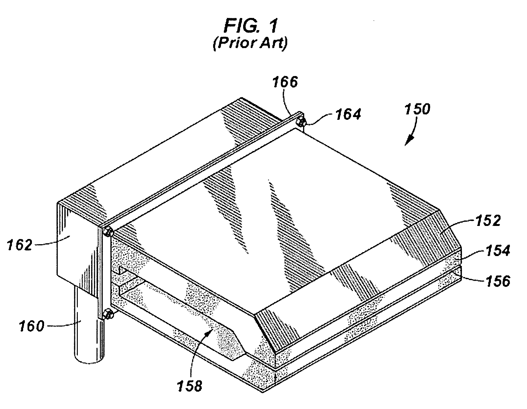
Not only are the fields of use quite different, but the nature of the molten material and fibers to be produced, and equipment being different (fibers vs. large pools of molten material, usage of burners to attenuate fibers vs. usage of burners for melting) leads to very different problems to be solved, despite the fact that decreased energy usage is a common goal of many industries, including both the float glass and mineral fiber industries.

Method used


Image

  • Burner apparatus and methods for making inorganic fibers
  • Burner apparatus and methods for making inorganic fibers
  • Burner apparatus and methods for making inorganic fibers

Examples


Embodiment Construction

[0065]In the following description, numerous details are set forth to provide an understanding of the present invention. However, it will be understood by those skilled in the art that the present invention may be practiced without these details and that numerous variations or modifications from the described embodiments may be possible.

[0066]The invention describes inorganic material fiberization burner apparatus and methods of using same. Although the invention is not limited to so-called “microfiber” production processes and systems, it is helpful to define the term as a starting point. As used herein, “microfibers” are defined as fibers having a mean diameter ranging from about 0.05 to about 3.5 micrometers, more typically from about 0.1 to about 1.0 micrometers. Microfibers produced by processes and systems of the invention may have a length to diameter ratio of at least about 5:1 and more usually from about 3000:1 to about 10:1. The length to diameter ratio of the microfibers ...


PUM

PropertyMeasurementUnit
diameteraaaaaaaaaa
combustion chamber pressureaaaaaaaaaa
mean diameteraaaaaaaaaa

Abstract

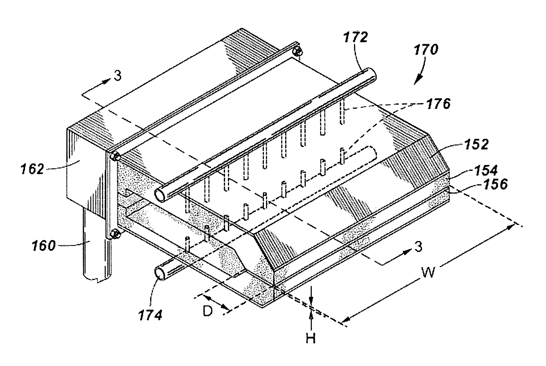
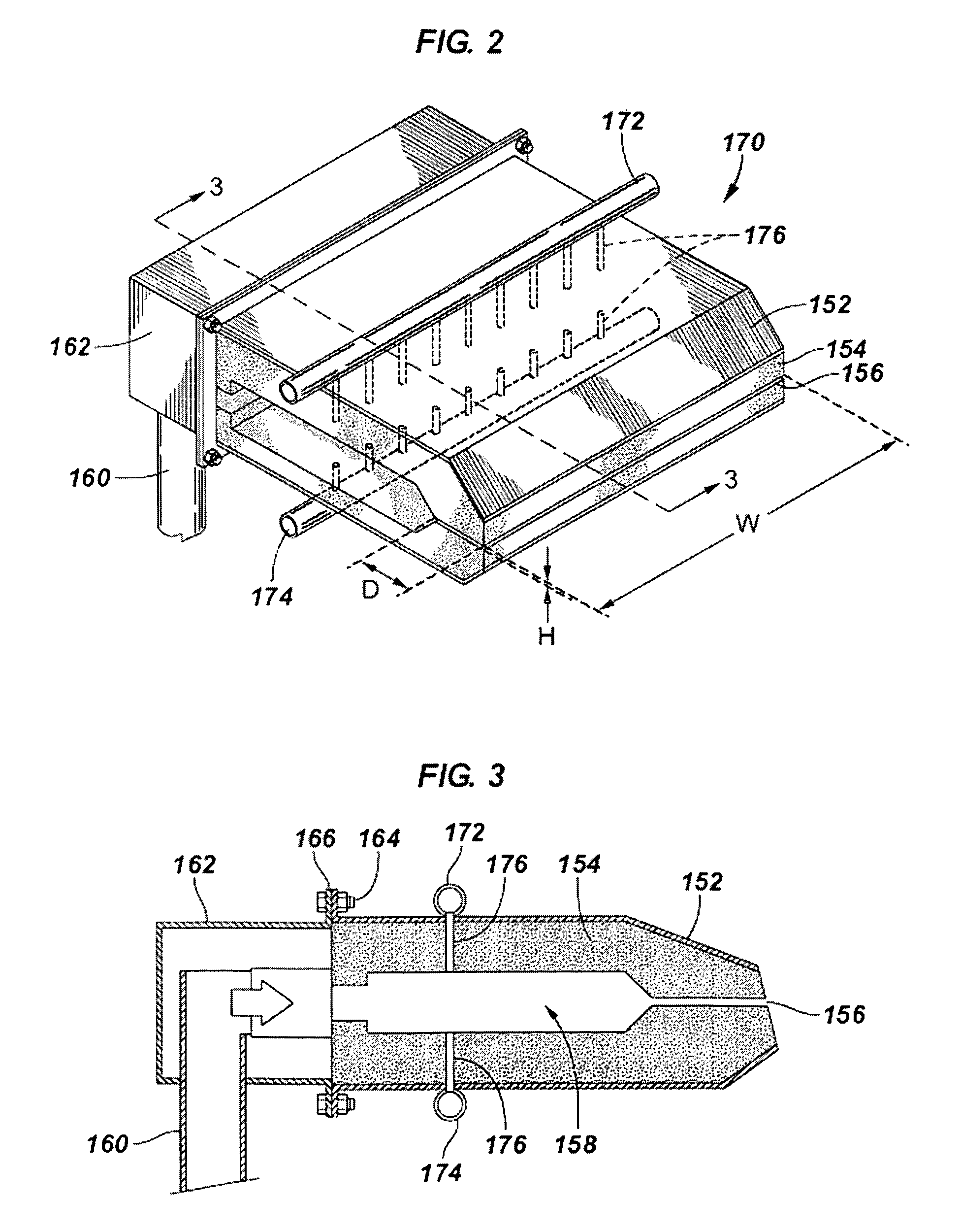
Inorganic fiber production burner apparatus and methods of use are disclosed. One burner includes a refractory block adapted to be in fluid connection with sources of primary oxidant and fuel, the refractory block having a fuel and primary oxidant entrance end and a flame exit end, the flame exit end having a substantially rectangular flame exit having a width greater than its height, the refractory block defining a combustion chamber and a second chamber fluidly connecting the combustion chamber and the flame exit end; and an oxygen manifold fluidly connected to the combustion chamber and adapted to route oxygen to the combustion chamber through a plurality of passages through the refractory block. This abstract allows a searcher or other reader to quickly ascertain the subject matter of the disclosure. It will not be used to interpret or limit the scope or meaning of the claims. 37 CFR 1.72(b).

Description

BACKGROUND OF THE INVENTION[0001]1. Field of Invention[0002]The present invention relates generally to the field of combustion burners and methods of use, and more specifically to burners and methods of use in flame attenuation fiberization processes producing inorganic microfibers and other fibers.[0003]2. Related Art[0004]One process for manufacturing fine diameter mineral fibers, e.g. discrete length, glass fibers typically ranging from about 0.2 microns to about 7.0 microns in diameter, is the flame attenuation process. In this process, an electrically or gas flame heated pot or melter containing a molten fiberizable material such as glass batch materials or preformed marbles are melted and drawn from a plurality of outlet orifices of a bushing to form continuous primary filaments. The primary continuous filaments are drawn from the heated pot or melter by pull rolls which also function to feed the continuous primary filaments into a high temperature, high energy, gas flame that...

Claims


Application Information

Patent Timeline
Patent Type & Authority Patents(United States)
IPC IPC(8): F23C3/00F23L9/06
CPCF23D14/20F23D14/32F23M5/00F23C2900/03005Y02E20/344F23M2900/05004F23D2214/00C03B37/065F23L7/007F23C6/047F23C2900/06041Y02P40/57Y02E20/34
Inventor BORDERS, HARLEY ALLENNIJAKOWSKI, MICHAEL R.THOME, WILLIAM J.MCKENZIE, RAYMOND L.
Owner JOHNS MANVILLE CORP
Learn More